Playing with Vixen Lights and LEDs
Some years ago, I saw this dance by collaboration between Akiba and Wrecking Crew Orchestra, and did some reading and found the lights were orchestrated using vixen lights software. I downloaded vixen v2 then and was very confused of what to do and how to do it, I didn’t invest more time in finding it out. I got discouraged, I let it be and moved on to other things. Vixen Lights does have a slight learning curve to it. Yesterday I was clean up downloads folder and found it sitting there and I took it to myself that I would figure this out and Figure out I did. Here is how I did it and hope it helps you too.
What is Vixen Lights?
An easy and intuitive way of controlling stuff. You can do a lot of stuff with vixen, I’m still discovering new things while playing around it. The primary application I’ve see is controlling lights with vixen, but it can be used to control more things, like switching AC loads, controlling motors and its speed etc. All this is done on a timeline, so you can control the precise timing of on/off of the thing that you are controlling. I’m using Vixen 3.x which is more stable that its predecessor 2.x, but I’ve experienced slight stability issues with 3.x as well. There is also a preview mode where in you create a scene and can visualize the elements of the scene without connecting any hardware, more on that later. All in all I love this piece of software and blame myself for not learning it sooner.
How did I make it?
First I’ll give a bird’s eye view of the process and then I’ll delved into details. When you open up vixen, first you’ll have to setup the display, this is where you define you inputs and outputs and you patch the inputs and outputs. Once that is done you start with new sequence, this window will have the elements that were defined in the setup display screen. Now add the effects and see your geek shine. I’m using the serial port connected to Arduino and vixen sends the data on the serial port and the data is read and interpreted on the Arduino and it takes the necessary action.
Detail Explanation
Now it’s time to get in to the nitty-gritty of the system. First I’ll describe what my hardware is and then I’ll describe how the software is configured.
Hardware Set up
I’m using an Arduino Mega, you can also use a Uno, I’m using mega as I have it on hand. There are 6 led attached to the IO pin of the Arduino, try to use the pin that have PWM, so that you can use more effects,and make sure you edit the code to match the pins that you are using. 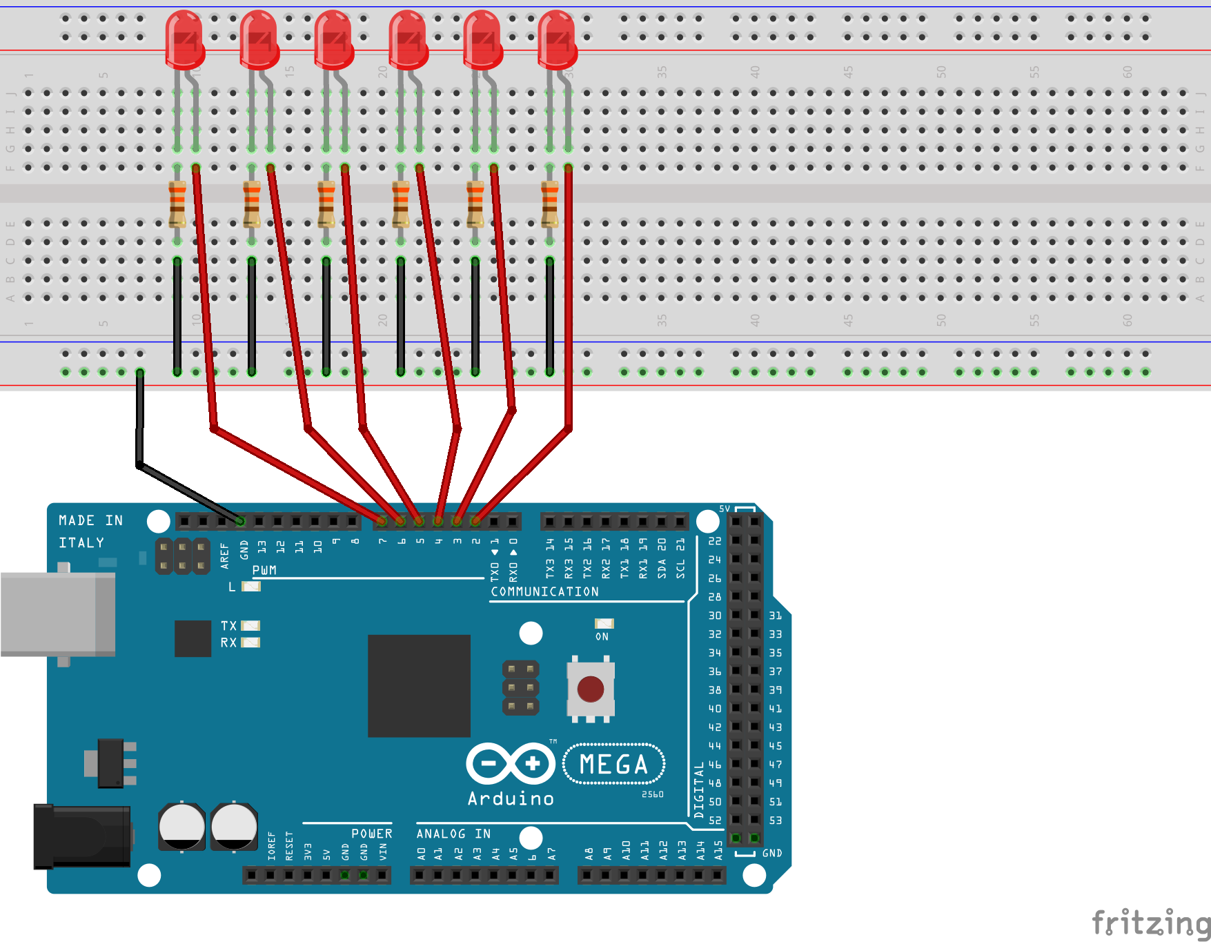
[caption id=“attachment_1741” align=“alignnone” width=“300”]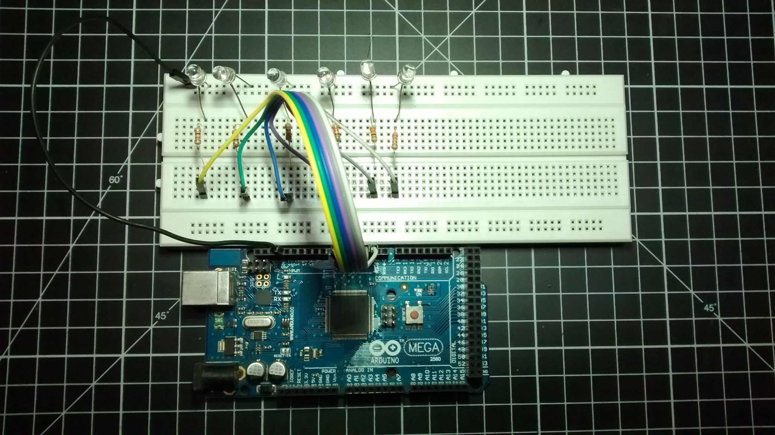 Hardware for Vixen Lights[/caption]
Now upload the following code on Arduino, you can read what it does, for those who don’t I’ll explain it further down the post.
//http://freaklabs.org/index.php/blog/chibi/wireless-lighting-control-using-arduino-and-vixen.html
//Modified my Hemal Chevli ([email protected])
#define MAX\_CHANNELS 6

int ch;
int state;
int chVal\[MAX\_CHANNELS\] = {0};
int pins\[\] = {2, 3, 4, 5, 6, 7};

enum states
{
  IDLE,
  DELIM,
  READ,
  DISP
};

void setup()
{
  for (ch=0; ch<MAX\_CHANNELS; ch++)
  {
    pinMode(pins\[ch\], OUTPUT);
    digitalWrite(pins\[ch\], LOW);
  }

  state = IDLE;
  ch = 0;

  Serial.begin(115200);
}

void loop()
{
  if (Serial.available())
  {
    switch (state)
    {
      case IDLE:
        ch = 0;
        if (Serial.read() == '+')
        {
          state = DELIM;
        }
        else
        {
          state = IDLE;
        }
      break;

      case DELIM:
        ch = 0;
        if (Serial.read() == '>')
        {
          state = READ;
        }
        else
        {
          state = IDLE;
        }
      break;

      case READ:
        chVal\[ch++\] = Serial.read();
        if (ch >= MAX\_CHANNELS)
        {
          ch = 0;
          state = DISP;
        }
      break;

      case DISP:
        state = IDLE;
        for (ch=0; ch<MAX\_CHANNELS; ch++)
        {
          analogWrite(pins\[ch\], chVal\[ch\]); // Write current values to LED pins

          /\*
          if (chVal\[ch\] > 0)
          {
            digitalWrite(pins\[ch\], HIGH);
          }
          else
          {
            digitalWrite(pins\[ch\], LOW);
          }
          \*/
        }
      break;
    }
  }
}
Arduino Code Explaination
The code structure is called a state machine, where arduino is in one of the four states, this can also be achived using if else structure but the switch statement is much more readable, first arduino looks for the start of the frame by looking for “+>” you can use any character of your choice, make sure you have the same characters in the vixen serial port settings. Once it read the start of the frame it will read byte value for all 6 channels and after the frame is read, it will write the values to the PWM pins, which inturn changes the brightness of the LEDs.
Vixen Software setup
Download Vixen Lights from here and start the software
[caption id=“attachment_1729” align=“alignnone” width=“253”]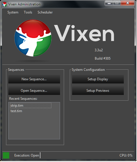 Vixen lights start-up screen[/caption]
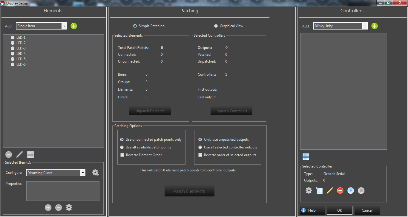
Go to setup Display
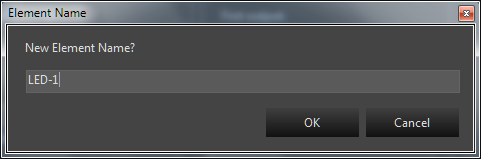
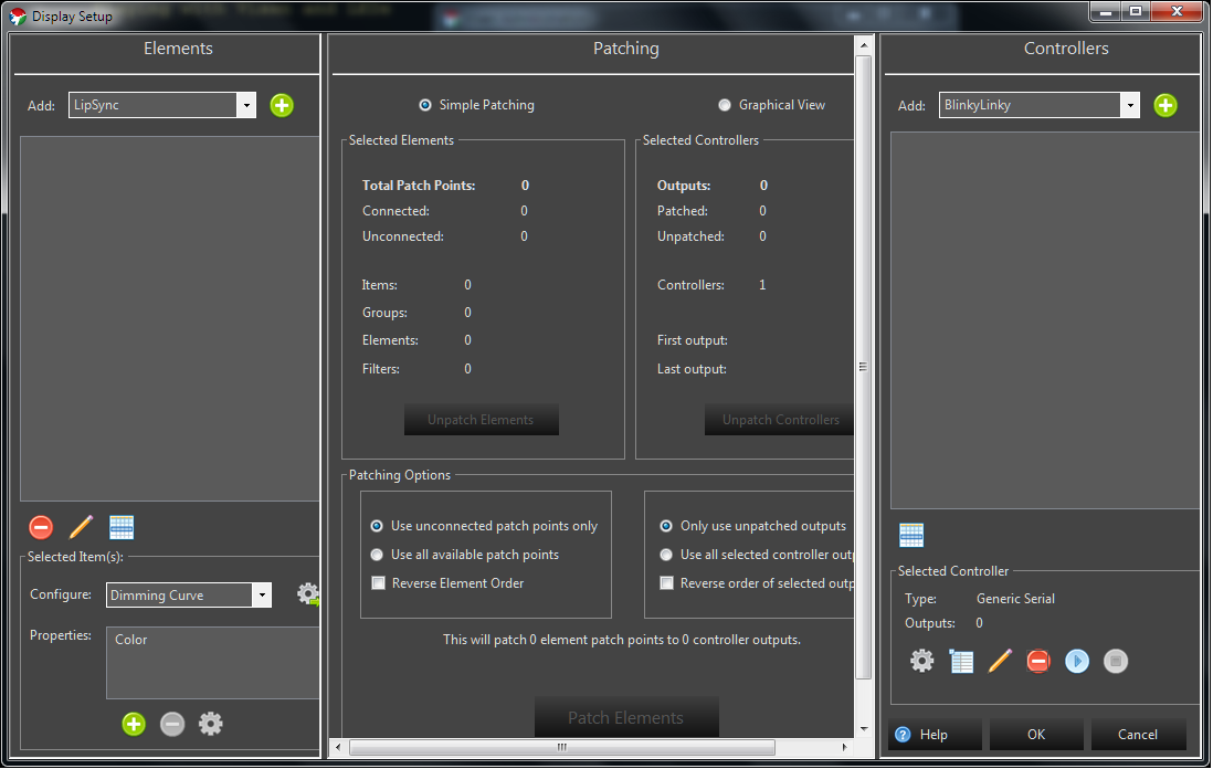 In the left column called Elements is what you want to control. These can be LEDs, motors etc. Now select “Single Item: from the drop down and click on the green plus sign button to add it. You will be prompted to set the name of the element, I’ve named it LED-1 as I’m using LEDs for control. Repeat adding element and add 6 items.
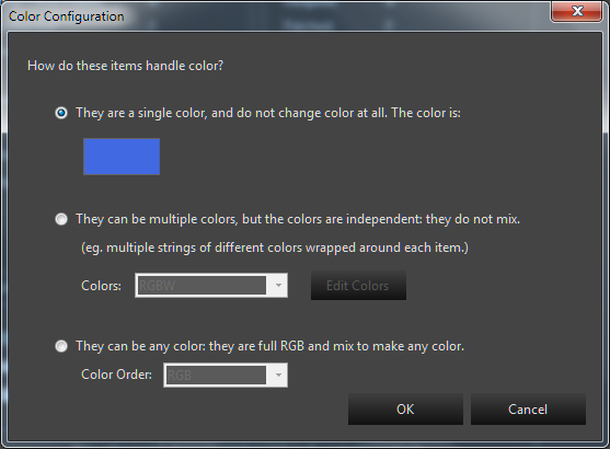
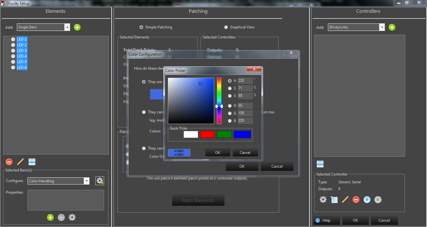
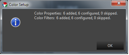
 Now we have to tell Vixen what is the type of LEDs we have connected, we are using single colour LEDs. Now select all the elements using shift key and go to “Configure” drop down and select “Color handling”, next click on the gear icon next to it and select single color option and change the colour. I’m using green LED, hence I’m using green colour, this step is optional, but when you are dealing with more elements it will be a must. Clicking ok will bring up a dialog box listing the configurations that were done.
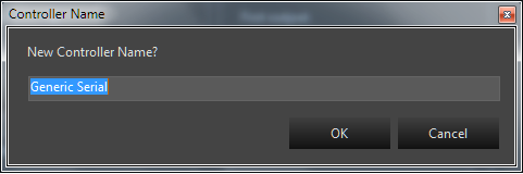
 Now we are done with the element, we go to the right column called Controllers. Select “Generic Serial”, the sequence data will be pushed on the serial port and the data is interpreted by Arduino and necessary action is taken.
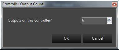
You will asked to enter the name of the serial port, I kept it default. Next you will be prompted to specify the number of outputs, since we are using 6 led, we will punch in the number 6 and click ok.
Now we are done with the element, we go to the right column called Controllers. Select “Generic Serial”, the sequence data will be pushed on the serial port and the data is interpreted by Arduino and necessary action is taken.
You will asked to enter the name of the serial port, I kept it default. Next you will be prompted to specify the number of outputs, since we are using 6 led, we will punch in the number 6 and click ok.
 Make user you have your Arduino connected. Now on the lower right column select the gear button to configure the serial port.
Check send a text header and enter “+>”, These characters will be added in the beginning of every frame, so on the Arduino if a frame is missed, Arduino can detect the start of new frame and start doing its stuff.
Make user you have your Arduino connected. Now on the lower right column select the gear button to configure the serial port.
Check send a text header and enter “+>”, These characters will be added in the beginning of every frame, so on the Arduino if a frame is missed, Arduino can detect the start of new frame and start doing its stuff.
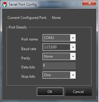
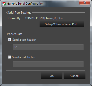 Click on “Setup/Change serial Port”
Select com port where the Arduino is connected and set the baud rate to 115200, keep the rest of the settings as it is.
Click on “Setup/Change serial Port”
Select com port where the Arduino is connected and set the baud rate to 115200, keep the rest of the settings as it is.
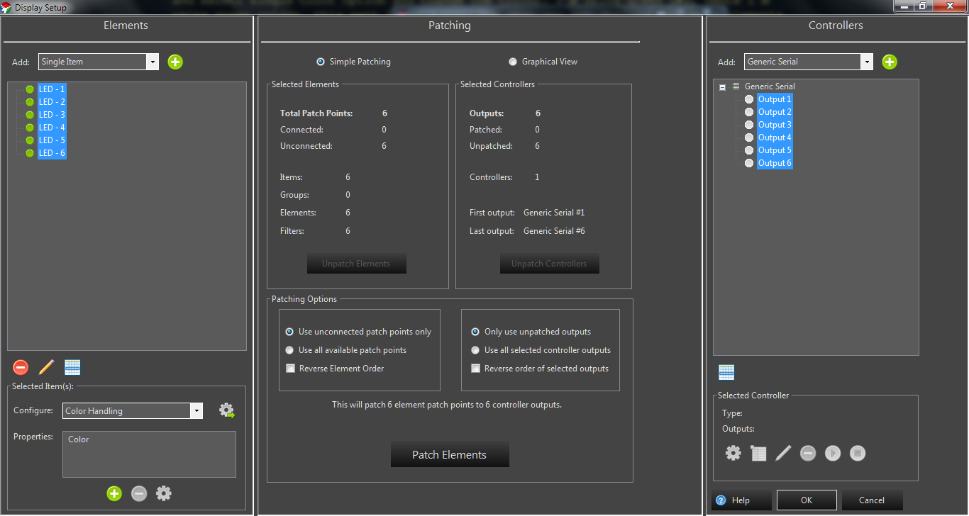
 You should see the RX led on the Arduino board blinking and if not, click on the stop button and then on play button. Now that data is being sent to Arduino, but these are just empty frames of data and has no information. Now we tie the elements to the controller which is called patching. Select all the elements on left column and all the outputs on the serial port on right and click on “Patch Elements”
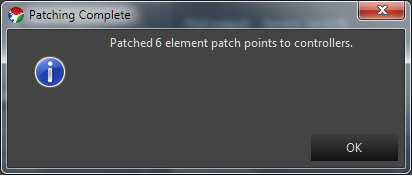
 You will get a confirmation
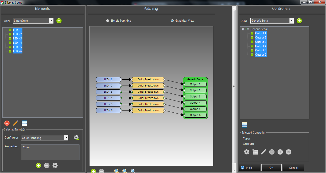
 Go to graphical view to see the graph
 Save all the settings by clicking “OK”.
Sequencing
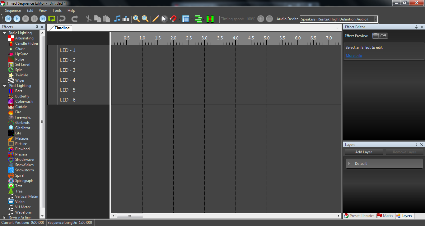
Next we click on “New sequence”
This shows the elements we defined before,
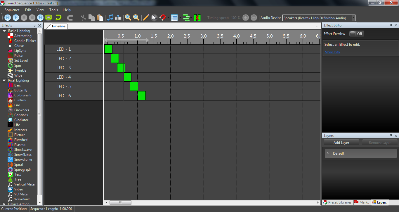
 Now drag “Set Level” on the time line, this defines the time when that LED will be on, you can resize the on time by dragging around, you can copy and paste the same block on different LEDs and create an animation.
Here is what I’ve made
Now drag “Set Level” on the time line, this defines the time when that LED will be on, you can resize the on time by dragging around, you can copy and paste the same block on different LEDs and create an animation.
Here is what I’ve made
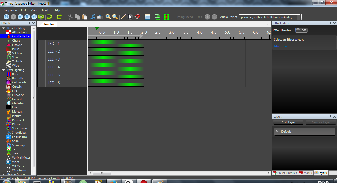
 Hit play button and watch the LED blink away. You can stop and make changes and click play again with the new sequence.
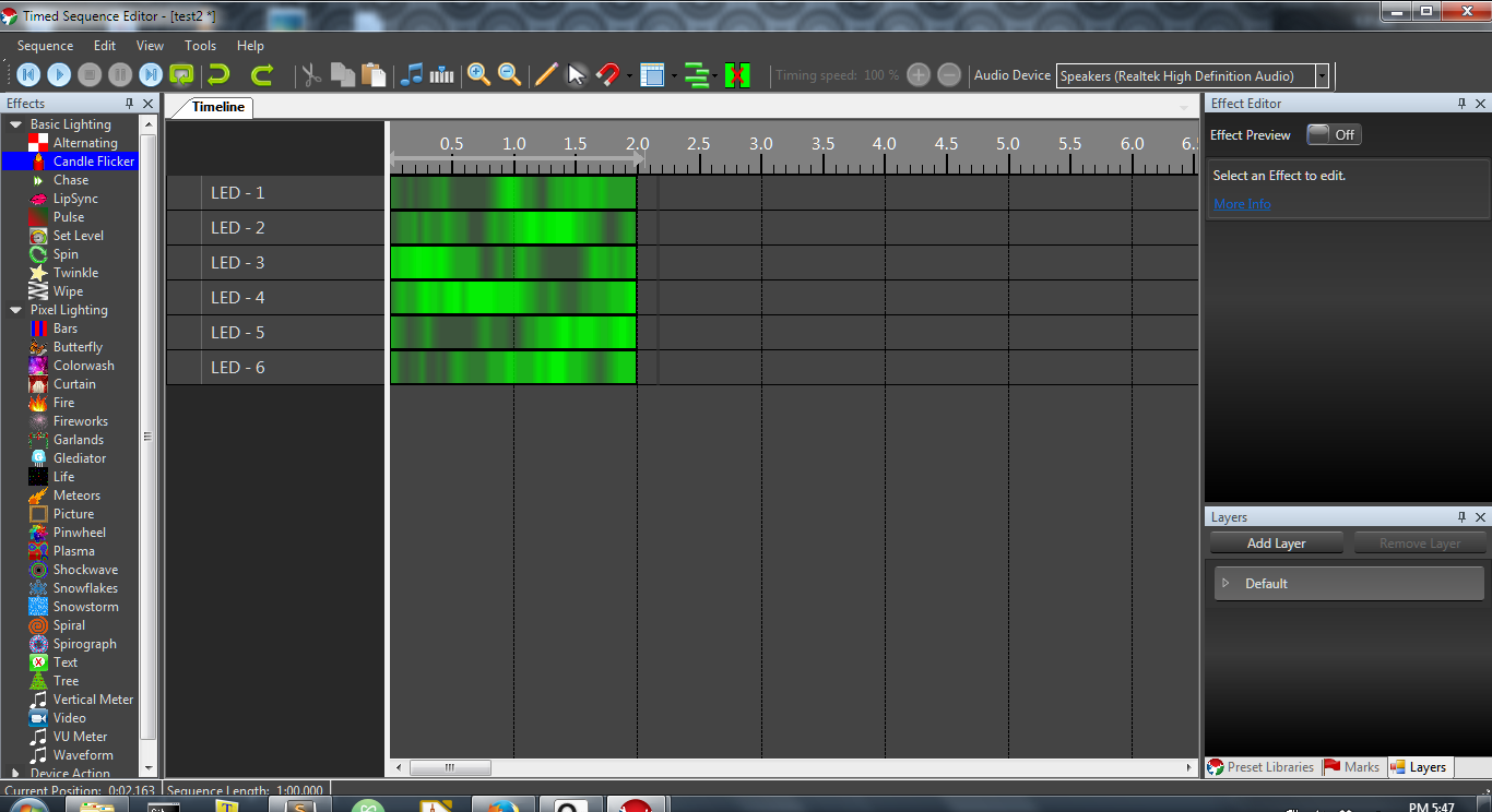
Here are some sequence with different effects.
Hit play button and watch the LED blink away. You can stop and make changes and click play again with the new sequence.
Here are some sequence with different effects.

No hardware No problem
If you have no hardware and still want to test out vixen or you want to simulate your sequence before running on a hardware, there is a way for that as well.
Go ahead and start Vixen and click on setup previews
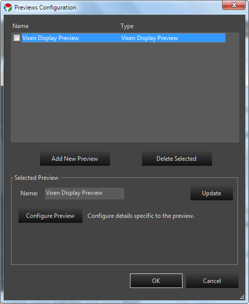
Now click on add new preview, if no previews are present, if present, click on configure preview. this will open a new window where you can place shapes and add images to simulate the sequence.
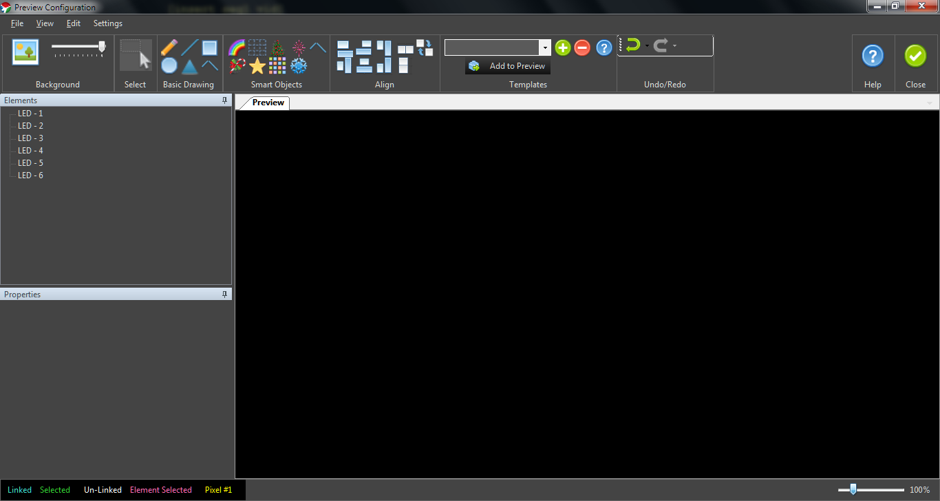 Previously defined elements will appear here. Now we can draw shapes and link the shapes with the elements, so when we play the sequence we can see the shapes light up according to the sequence, pretty cool right.
First select the element that you want to draw the shape for, then select the shape that you want to define. As a result the shape will appear blue, which means it’s linked to the element, go ahead and select elements and draw their corresponding shapes, now click on all the elements one by one and its corresponding shape will turn pink in colour. Preview window can only be closed by unchecking in the setup preview section. Here is a short video of the preview
https://www.youtube.com/watch?v=hHlK7NONKsI
Resources
*   **Forums**: http://doityourselfchristmas.com/forums/forumdisplay.php?96-Vixen-3
*   **Vixen Documentation**: http://www.vixenlights.com/vixen-3-documentation/
*   **Element 14 tutorial**: https://www.element14.com/community/community/arduino/blog/2014/03/28/sequencing-leds-using-arduino-and-vixen-lights
*    **Akiba tutorial** http://freaklabs.org/index.php/blog/chibi/wireless-lighting-control-using-arduino-and-vixen.html
*    **A German site I found**(translated): https://translate.googleusercontent.com/translate\_c?depth=1&hl=en&ie=UTF8&prev=\_t&rurl=translate.google.co.in&sl=auto&tl=en&u=http://www.technikfreak.ch/2016/10/09/digitale-weihnachtsbeleuchtung-selbst-gebaut-teil-3/&usg=ALkJrhj11ZxZiR3oHOoiZOZcXk5OVlv97A
Comments:
alessandro lazzari - Dec 0, 2017
great project, really a good job. But it happens that sometimes arduino does not update the lights, coma ever, is my unit damaged?
Thanks. Ya I too faced the same issue, vixen sometimes stops the data or other times arduino hangs up. I reset the whole system and it starts working. Vixen works really well, until it doesn’t. :)
Thanks for the write up- Can one use or modify this code to use 2811 or 2812 pixel strips instead of single leds, and each can have different effect? like-while one strip has a twinkle effect, other multicolor and other fade…Thanks in advance, MJD
yes, its possible to drive pixel strips with vixen, I haven’t tried it yet. maybe this can help http://doityourselfchristmas.com/forums/showthread.php?31079-Arduino-code-for-driving-RGB-Addressable-pixels-from-Vixen Cheers!
This is a great guide. Thanks for sharing it. I am running into problems. I only have one led coming on. I ran a test sketch and the leds work as expected. In my sequence only the LED-1 comes on and follows the sequence.
I can’t seem to get it to work on my uno, is there a different program for the uno as opposed to the mega?
It should work with UNO, I’ve not used any mega specific code. It was a hit and miss when I was doing this.