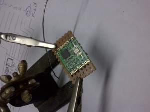
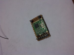
2mm headers to 2.5mm header
2mm header (SEO shenanigans)
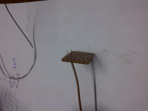
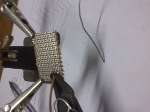
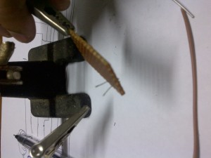
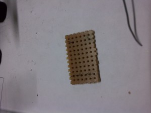
Its a simple hack to use boards with 2mm spacing headers with the usual 2.5mm headers, the pictures are worth a thousand words. You can use this with your most esp8266 or xbees.
Steps
Measure
Strip a wire, and give its a twist.
Insert it from the solder side
Solder it
Snip it
Do it again as per your need
Done
Place the 2mm header spacing board, move the wire with pliers where they need to be soldered
Soldered
Solder the 2.5mm headers
x 2
Use them as daughter boards.
Comments:
Castellated Breakout is Pitchin’ Brilliant! | Hackaday - Feb 2, 2015
\[…\]over at Black Electronics came up with a hack to convert odd-pitch modules to standard 2.54mm / 0.1″. The process looks simple once you see the detailed pictures on his blog. He’s using the
\[…\] \[…\]over at Black Electronics came up with a hack to convert odd-pitch modules to standard 2.54mm / 0.1″. The process looks simple once you see the detailed pictures on his blog. He’s using the
\[…\] \[…\]over at Black Electronics came up with a hack to convert odd-pitch modules to standard 2.54mm / 0.1″. The process looks simple once you see the detailed pictures on his blog. He’s using the
\[…\] \[…\]over at Black Electronics came up with a hack to convert odd-pitch modules to standard 2.54mm / 0.1″. The process looks simple once you see the detailed pictures on his blog. He’s using the
\[…\]I’ve got a SOYO-BT24G03 board that has castellated spacings of less than 1.27mm/.05".. any suggestions? I’m thinking just laying out a schmartboard style pcb but I wonder how is this usually done?
If you need access to few pins, you can use the above method else I’d suggest using a breakout board.
topfuck123gals.mobi topfuck123gals.mobi u2ym
Archives
Tags


