Altium Release Procedure
When I first started using Altium, I found the OutJob file a bit confusing. After taking Robert Feranec’s course, I understood it better, but it still involved moving a lot of files around to the release folder after they were generated. Over time, I’ve streamlined the OutJob file so that now, when it generates files, they automatically go into their designated folders, ready to be zipped and sent to the manufacturer.
In this post, I’ll walk you through how I set it up.
Initially, in the OutJob file, I had a single container for generating files and one for generating PDF’s and would manually choose which files to generate in both containers, then move the files to the release folder. This caused changes in the OutJob file, which created version control issues and I was not sure if I made any new changes.
With my current setup, the OutJob file stays unchanged, even when I generate new files after making updates. I just select the container and hit generate content.
The first step is to define all the documents you’ll need. Typically, these include:
- PCB files (containing drill and Gerber files and drill files)
- Assembly files (including the Bill of Materials, a position CSV file, and a PDF of the top and bottom assembly with designators)
- 3D views (of both the top and bottom of the board)
I also like to include a schematic print in the OutJob, though I don’t send that to the manufacturer.
I prefer to keep all my files stored locally and not rely on Altium 365 as part of my workflow.
Here’s an example of how my OutJob file and folder structure look.
The files are prefixed or suffixed with the project name.
Release Files
├── Assembly_Files
│   ├── Assembly Drawings.PDF
│   ├── Bottom PCB 3D Print.PDF
│   └── Top PCB 3D Print.PDF
├── Bill Of Materials
│   ├── Bill of Materials-ProjectName.xlsx
│   └── Status Report.Txt
├── Gerber_Files
│   ├── Gerber Files
│   ├── NC Drill Files
├── Pick and Place
│   ├── Pick Place.csv
├── Schematic_Prints
│   └── ProjectName-Schematic Prints.PDF
└── Step_Export
    ├── ProjectName-Board.step
    └── Status Report.Txt
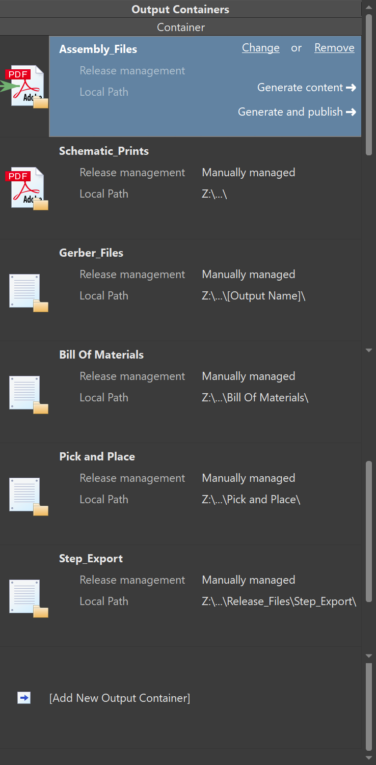
Here are the containers
 And here is how the rest of the OutJob file looks like.
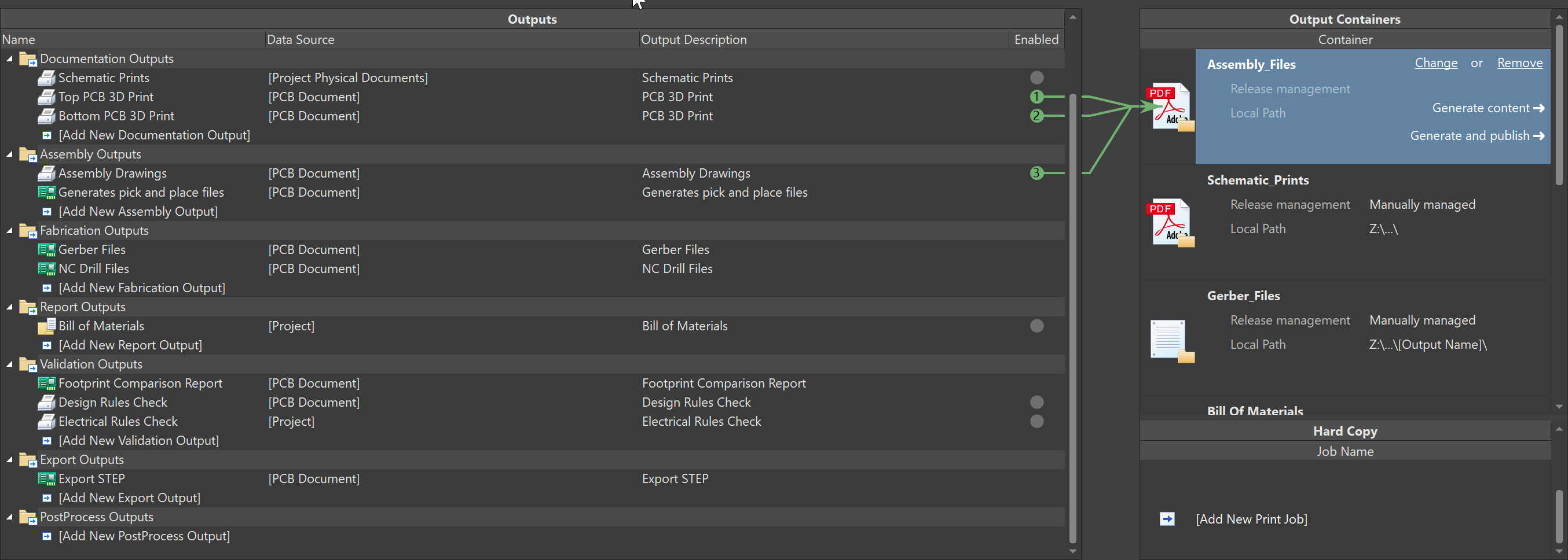
Each container in the OutJob file has fixed files that are generated, and the path for each container is set up so that it automatically creates a folder under the release folder.
Most of the customized output is the Assembly Drawing output, that clearly shows how each component is assembled.
To use the same OutJob file across all your projects, it’s important to maintain consistent layers throughout. This consistency begins with the footprint component library. Every component created or imported from external libraries should follow the same layer structure you use in your footprint library.
When you create a PCB document (PcbDoc), all the layers are carried over from the footprints. The OutJob file also defines these layers, so you can use the same OutJob file across different projects. If the layers don’t match, you’ll need to manually adjust the output settings, otherwise it can lead to inconsistencies.
Here’s an example of what a sample assembly file looks like.
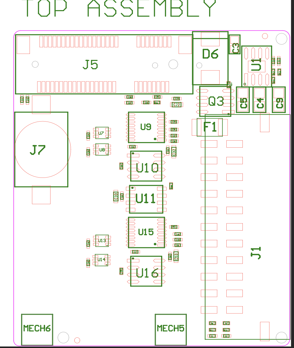
The assembly drawing not only shows the component designators but also includes the pad locations for easy reference by the manufacturer.
By using this OutJob file, I’ve rarely encountered production blockers from manufacturers, as all the necessary information is neatly organized in the release folder.
This version should be clearer and easier to follow!
Ciao!
Archives
Tags