Arduino based Waveform Generator
New Tool- Waveform Generator
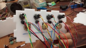
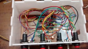
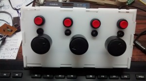
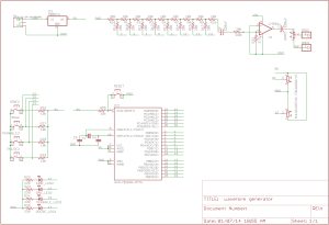
Finally, after sitting in the TODO list for a long time, I’ve made a basic wavefrom generator based on arduino, made using this instructable as reference. I had an enclosure laying around which has incorrect dimensions for the project in which it was supposed to be used. The instructable had the sch for Waveform generator shield, I modified it a bit so its a stand alone system. I had to carefully plan the layout as it uses too many resistors, The DAC is done using R-2R network of 10k and 20k, in place of 20K I used two 10k in series. the output of DAC network goes to LM386 audio amp. Below are some build and testing pictures. It can generate 4different types of waves, sine, pulse,sawtooth and triangle, with frequency and amplitude control, and pulse width control for the pulse wave form. For each wave the corresponding LED lights up.
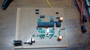
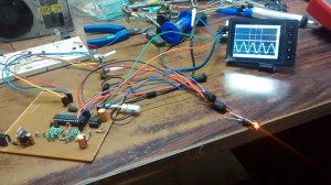
Sine Waveform
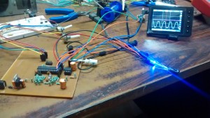
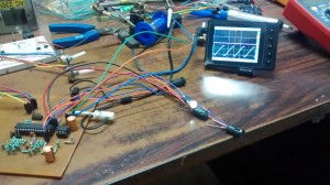
Sawtooth Waveform
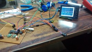
Triangle Waveform
Pulse waveform
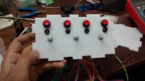
Building the enclosure
Schematic
****Please note the switches are connected together are connected to ground.
Schematic: waveformgenerator (Save the file and change the extension to .sch ,made with eagle 6.5.0)
Videos
https://www.youtube.com/watch?v=5cfE3ZlM-cQ
Testing on speaker
https://www.youtube.com/watch?v=hY92LN-OKG8
Comments:
Arduino based waveform generator | RLabs - Jul 6, 2014
\[…\]Chevli made this Arduino based waveform generator. He wrote a post on his blog detailing its
\[…\]can you add which potis you used and the maximal frequency?
I’ve used all 5k pots and frequency max frequency is 50kHz
ty
hello hemalchevli, can you post code for pure mega328 (without arduino bootloader)?
It can be done, but I can’t give you an ETA.
Hi, mind putting the eagle files up for download? I like to generate a layout for etching…. thanks!
Updated!
Hello,can we build this on Uno R3?
Hi, Its based on ATMEGA328, so yes it can be made on an UNO.
Thanks for the real quick response,i just stimulated it on proteus, here in the given schematic out of 4 terminals of push button the pins which are on same side are shorted and one of the shorted terminal is connected to Resistors, can you tell me bout the other side of the PushButtons, i mean they are just shorted and left alone, is it okay to isolate them? or we need to connect them to Ground?
Dude, thanks for the this, I made a mistake in the schematic, the left side of the switches are indeed connected to ground. I’ll correct it asap. Thanks again! :)
:)
Is Vin LM328 is powered by 9V.
Yes it is.
In the original scheme Instructables Push Button Switch
\[Sine, Saw, Triangle, Pulse\]points 1 and 2 are connected to GND. In your diagram they are only connected together but not to GND. Is this a mistake on your schematic?
yes they are connected to ground. I’ll update the post now.
Can you give the correct code because there are errors. The oscilloscope shows me only the square-wave signal. People write about będach code on Instructables.
function_generator.ino.zip Is this code is 100% correct. reading the posts are reported bugs in the code. The oscilloscope shows me only the square-wave signal ..
Its already listed above, it is right after the schematic image.
Hi I modified the circuit to use just 1 analog line for the switches and also added a nice 1602 display showing me the frequency and mode .
Sweet, can share a photo of the same?
Hi ,, I did draw the schematic on paper , as soon as i transfer it to design the pcb i will upload the files and code
Join the discussion… Hi, Jason Markham Will you please upload the modified code and the schematic having added the 1602 display.
\[…\]http://localhost/black_electronics/arduino-waveform-generator/. Diakses pada tanggal 1 Mei 2017.
\[…\]Archives
Tags
