Carrier board design - Part 2
Transmission Line
Continuing from our last week’s post, today we will look at transmission lines.
This can be confusing to understand, as from the beginning we are used to treating circuits with currents and volts. Now we must understand the voltage and currents we were studying are the consequences caused by electromagnetic waves.
So, what is a transmission line? In the simplest form, it is a pair of two conductors that guide the electric and magnetic field from one point to another.
Here I’m using mechanical waves as an analogy, I read about this analogy in a book by Lee Ritchey Right the first time. This analogy helped me immensely in understanding transmission lines and reflections in them.

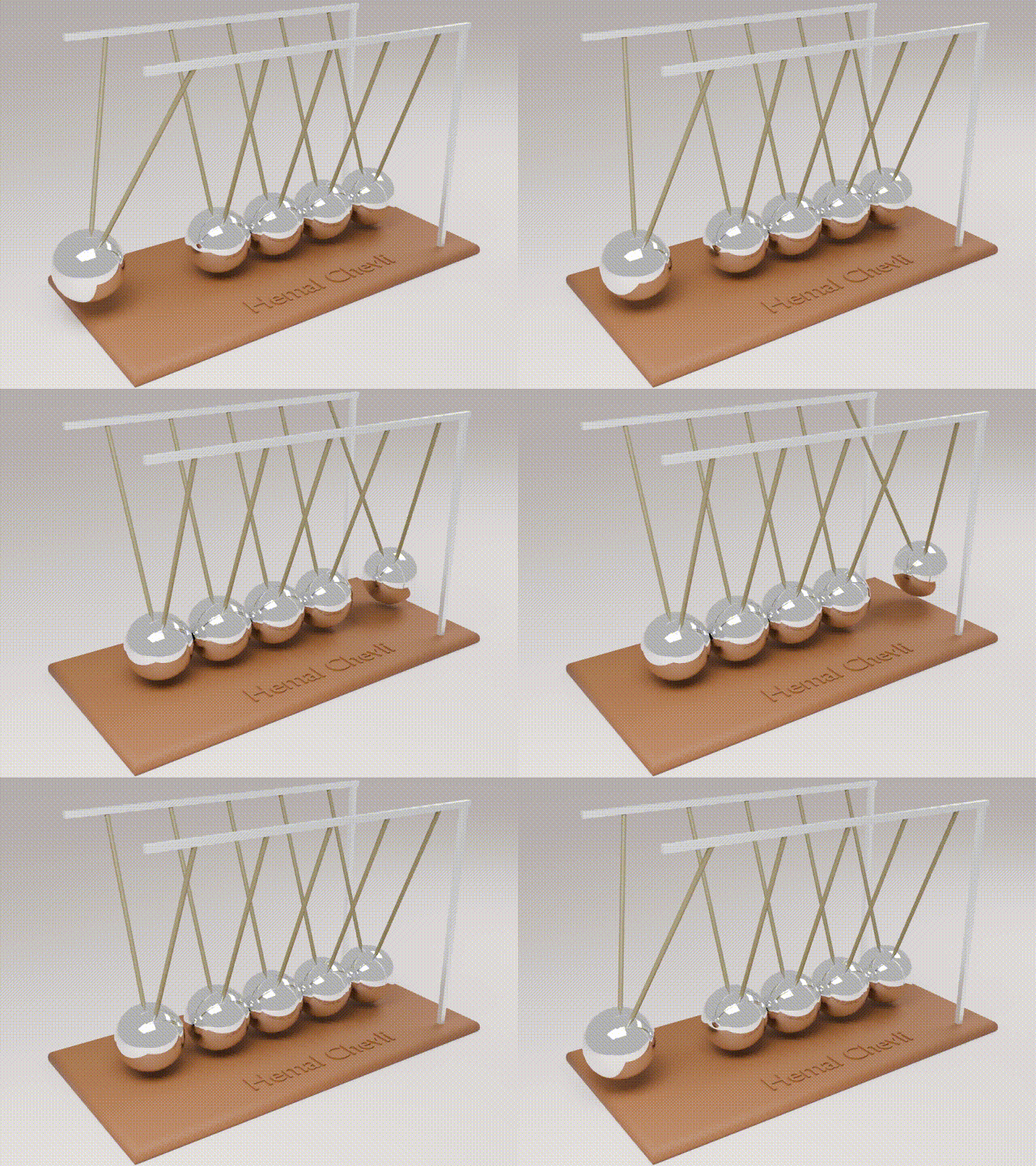
Here we have a newtons cradle, if we lift one end and let go, the energy is transferred through the intermediate balls and reaches the last one, since there is nothing there at the end to stop it, it swings up and hits back, this is called wave reflection. In the same way when we launch a signal from the driver and the other end is open, we get the wave reflected back.
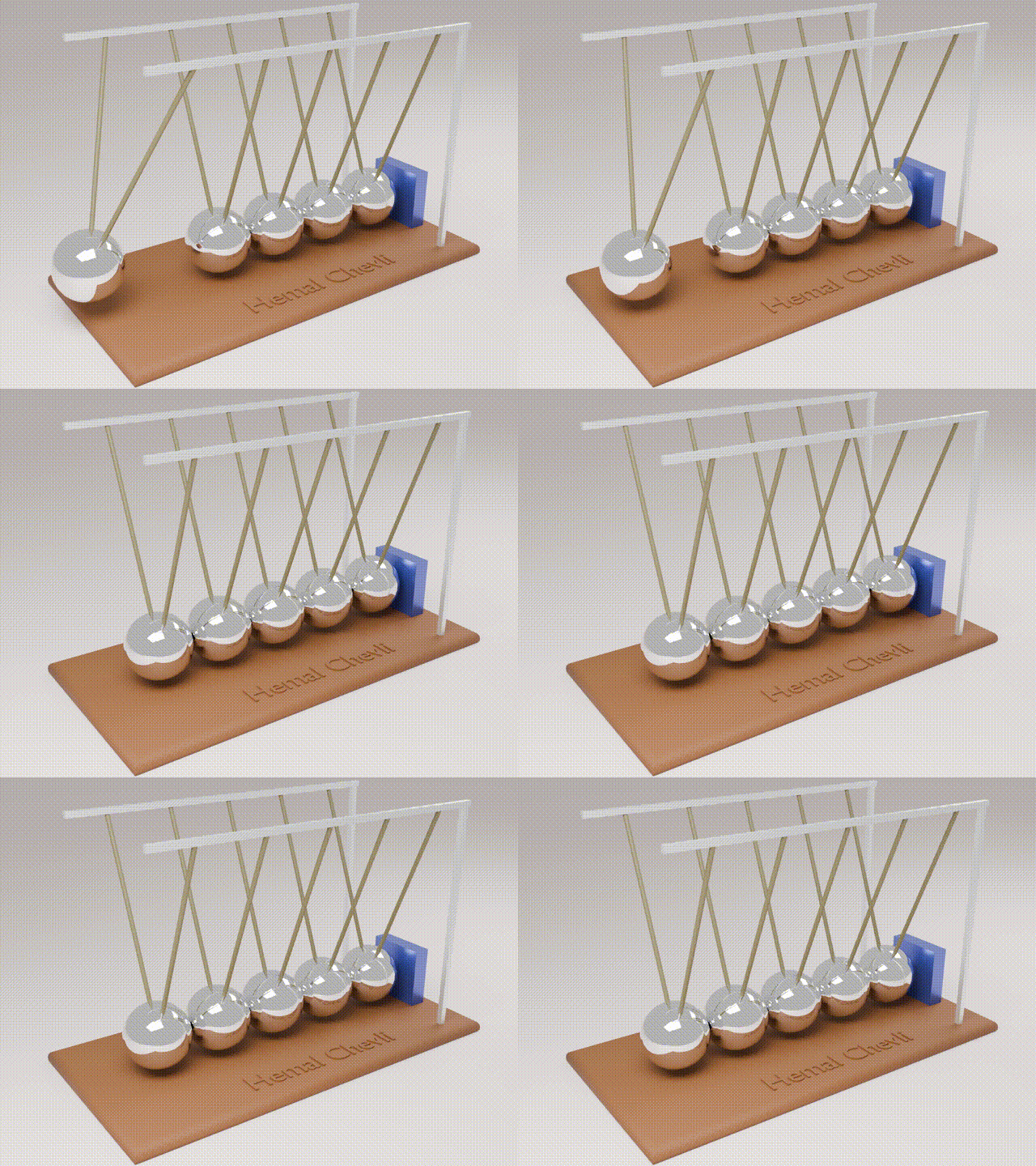
If we have a damping material that absorbs the energy from the last ball, then there is no reflection and in electronics speak we call this parallel termination.

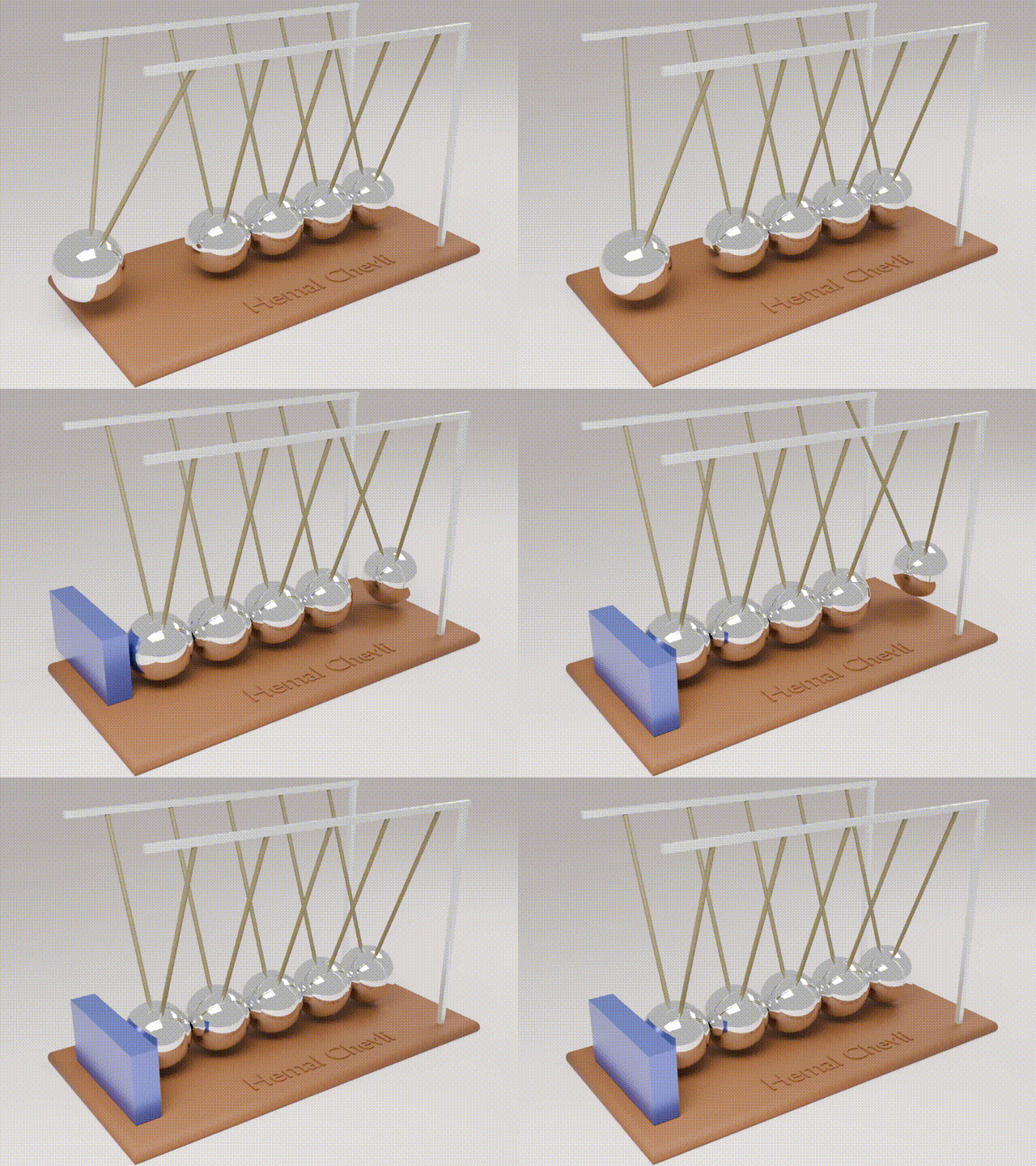
Series termination is when there is a damping system at the source.

In general reflections should be avoided, because the affect the signal integrity. We will talk about reflections in depth in future parts of the blog post.
There are several types of transmission lines, based on the how the two conductors (trace and ground plane) are positioned with respect to each other.
The unit of impedance is ohm, the characteristic impedance depends only on the geometry of the trace and the distance from the plane. One would think why it does not depend on the length. Yes, its true the resistance of a TX line is quite different between a wire of 10 cm compared to 10 miles. But the characteristic impedance will be same if there is no change in the geometry of the trace.
The characteristic impeadnce is the ratio of the amplitude of voltage wavefrom over the current waveform.
Say an op-amp has current as input and voltage as output, the unit of gain will be ohms. But that has nothing to do with resistance in this case.
The only difference between electromagnetic waves running on circuits and the light we see is frequency. Once you understand this, on PCB the same rules apply when managing digital, analog and rf signal. All of them depend on the voltage waveform used to convey the information.
That is, for this post, next week on Thursday we will go deeper into the high-speed concepts and talk about reference planes, reflections and stubs etc.
LLMs were not used in creating this post nor diffusion models for creating images.
Archives
Tags