First Encounter with Inductive Sensor
Operating Principles for Inductive Proximity Sensors
Inductive proximity sensors are used for non-contact detection of metallic objects. Their operating principle is based on a coil and oscillator that creates an electromagnetic field in the close surroundings of the sensing surface. The presence of a metallic object (actuator) in the operating area causes a dampening of the oscillation amplitude. The rise or fall of such oscillation is identified by a threshold circuit that changes the output of the sensor. The operating distance of the sensor depends on the actuator’s shape and size and is strictly linked to the nature of the material
Sensitivity when different metals are present. Sn = operating distance.
Fe37 (Iron)
1 x Sn
Stainless steel
0.9 x Sn
Brass- Bronze
0.5 x Sn
Aluminum
0.4 x Sn
Copper
0.4 x Sn
Click Here to go definition of terms .
Outputs:
DC Voltage
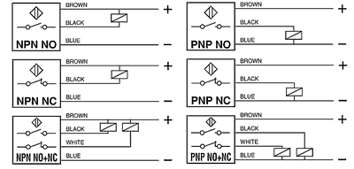
2 wire DC: These sensors contain an output amplifier with the function N.O. or N.C. that can pilot a load connected in series. In this system a residual current flows through the load even when in the open state and a voltage drop occurs to the sensor when it is in the closed state. Attention must be paid to these restrictions when selecting relays or electronic controls to be used with these sensors. They are compatible with P.L.C. units.

3 & 4 wire DC: These amplified D.C. sensors contain an output amplifier. They are supplied as 3 wire with function N.O. or NC and as 4 wire with complementary outputs (NO + NC) in the types NPN and PNP. Standard version include protected against short circuit, protected against polarity and peaks created by the disconnection of inductive loads. They are compatible with P.L.C. Units

Analog & Linear: In these 3 wire amplified sensors a current or voltage output varies in proportion to the distance between the sensor and a metallic object.

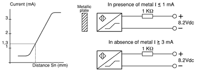
NAMUR: These are 2 wire non-amplified sensors whose current varies in the presence of a metallic object. The difference between these sensors and traditional sensors is the absence of amplifier trigger stages. Their current and voltage limits allow them to be used in hazardous (explosive) environments when used with approved amplifiers. In standard applications (normal atmospheres) the sensor must be used with amplifier units ALNC, ALN2 or similar.

AC Voltage 2 wire AC: These are two-wire sensors that contain a thyristor output amplifier. In this system a residual current flows through the load even when in the open state and a voltage drop occurs to the sensor when it is in the closed state. Attention must be paid to the minimum switching current, residual current and voltage drop when selecting low consumption relays or high impedance electronic controls to be used with these sensors. They are compatible with P.L.C. Units

Experimentation:
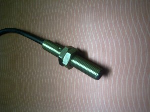
So, today, I got my first inductive sensor,its a NPN NO, with Sn=1.5mm, diameter 6mm length 45mm, with 3-24v supply,and tested it at 5v and 12v.
Its got a smd led in its body to show the on/off state, on means object is closer than 1.5mm
Wires:
Red : +V
Black: Gnd
Blue :Signal
when testing at 5v, when the object away led on sensor is off, signal line is a +1v, and when the object is in range, led on sensor goes off and the signal is at 0V.
Next step, connect it to a micro controller and do some switching.
UPDATE:24-dec-12
Switched a led using the sensor.
Test Video
http://www.youtube.com/watch?v=rk1XnuA7p-4
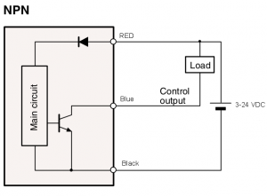
The Schematic
This test was done where the noise was less than that in industry, adding a capacitor between base and ground is advisable, also a resistor between the sensor ground and battery negative terminal, if there is a too much noise, and this will stop the ground from jumping.
Now the signal can be interfaced with the micro-controller for further processing
Definition of terms:
NO (normally open): A switch output that is open prohibiting current flow when an actuator is not present and closes allowing current flow when an actuator is present.
NC (normally closed): A switch output that is closed allowing current flow when no actuator is present and opens prohibiting current flow when an actuator is present.
NPN Output: Transistor output that switches the common or negative voltage to the load. The load is connected between the positive supply and the output. Current flows from the load through the output to ground when the switch output is on. Also known as current sinking or negative switching.
PNP Output: Transistor output that switches the positive voltage to the load. The load is connected between output and common. Current flows from the device’s output, through the load to ground when the switch output is on. Also known as current sourcing or positive switching.
Operating Distance (Sn): The maximum distance from the sensor to a square piece of Iron (Fe 37), 1mm thick with side’s = to the diameter of the sensing face, that will trigger a change in the output of the sensor. Distance will decrease for other materials and shapes. Tests are performed at 20ºC with a constant voltage supply. This distance does include a ± 10% manufacturing tolerance.
Power Supply: The supply voltage range that sensor will operate at.
Max Switching Current: The amount of continuous current allowed to flow through the sensor without causing damage to the sensor. It is given as a maximum value.
Min Switching Current: It is the minimum current value, which should flow through the sensor in order to guarantee operation.
Max Peak Current: The Max peak current indicates the maximum current value that the sensor can bear in a limited period of time.
Residual Current: The current, which flows through the sensor when it is in the open state.
Power Drain: The amount of current required to operate a sensor.
Voltage Drop: The voltage drop across a sensor when driving the maximum load.
Short Circuit Protection: Protection against damage to a sensor if the load becomes shorted.
Operating Frequency: The maximum number of on/off cycles that the device is capable of in one second. According to EN 50010, this parameter is measured by the dynamic method shown in fig. 1 with the sensor in position (a) and (b). S is the operating distance and m is the diameter of the sensor. The frequency is given by the formula in fig. 2.
Repeatability (%Sn): The variation between any values of operating distance measured in an 8 hour period at a temperature between is 15 to 30ºC and a supply voltage with a <= 5% deviation.
Hysteresis (%Sn): The distance between the “switching on” point of the actuator approach and the “switching off” point of the actuator retreat. This distance reduces false triggering. Its value is given as a percent of the operating distance or a distance. See Fig. 3
Flush Mounting: For side by side mounting of flush mount models refer to Fig. 4a. Non-flush mount models can be embedded in metal according to Fig. 4b. for side by side refer to fig. 4c. Sn = operating distance.
Protection Degree: Enclosure degree of protection according to IEC (International Electrotechnical Commission) is as follows: IP 65: Dust tight. Protection against water jets. IP 67: Dust tight. Protection against the effects of immersion
Mounting Tips
Inductive sensors are often specified based on their sensing distance and housing geometry. But you must also be aware of any mounting restrictions that might apply to the specific sensor chosen for the application. Various types of sensors require different considerations when they are mounted to a bracket or machine component. Mounting conditions may restrict the close proximity of any non-target metal in the area around the sensor mounting zone. The effect of the surrounding metal, located within the electromagnetic field generated by the sensor, may result in unintended consequences for the operation of the equipment. Depending upon the sensor, this metal may cause pre-damping of the sensor oscillator resulting in:
- False triggering
- Temperature instability
- Sensor latch-on effects
Several mounting options are available:
Flush mount = embeddable mounting = shielded sensor These sensors incorporate an electromagnetic shield positioned around the inductive coil that minimizes the effect of surrounding metal. They normally have the widest range of mounting options and the best immunity to mutual interference of nearby sensors.
Non-flush mount = non-embeddable mounting = unshielded sensor Sensors in this group have no electromagnetic shielding present around the inductive coil system and, therefore, are strongly affected by surrounding metal. These sensors normally have the longest sensing ranges, but require the largest amount of metal-free area around the mounting zone.
Semi-flush mount = quasi-embeddable These sensors have partial electromagnetic shielding present around the inductive coil. This partial shielding helps to minimize the effect of surrounding metal. Semi-flush mount sensors provide longer range than flush-mount sensors for the same housing size, but have some mounting restrictions that limit the metal allowed in the mounting area.
 Notes about this image:
- The red area shows the metal-free mounting zone required by different sensor types
- Unshielded sensors have a wider radiated magnetic field
- Flux lines have a higher field density nearer the coil system
- Mounting metal closer to the coil will have a more significant effect on pre-damping
Having taken a look at the different inductive sensor types, it’s pretty clear that based on the particular sensor type and mounting conditions or environment, each one calls for its own approach when it comes to mounting procedures.
Comments:
Hemal Chevli - Dec 5, 2012
test
Archives
Tags


