GPIO Hacker Board Timelapse on Core One
Overview
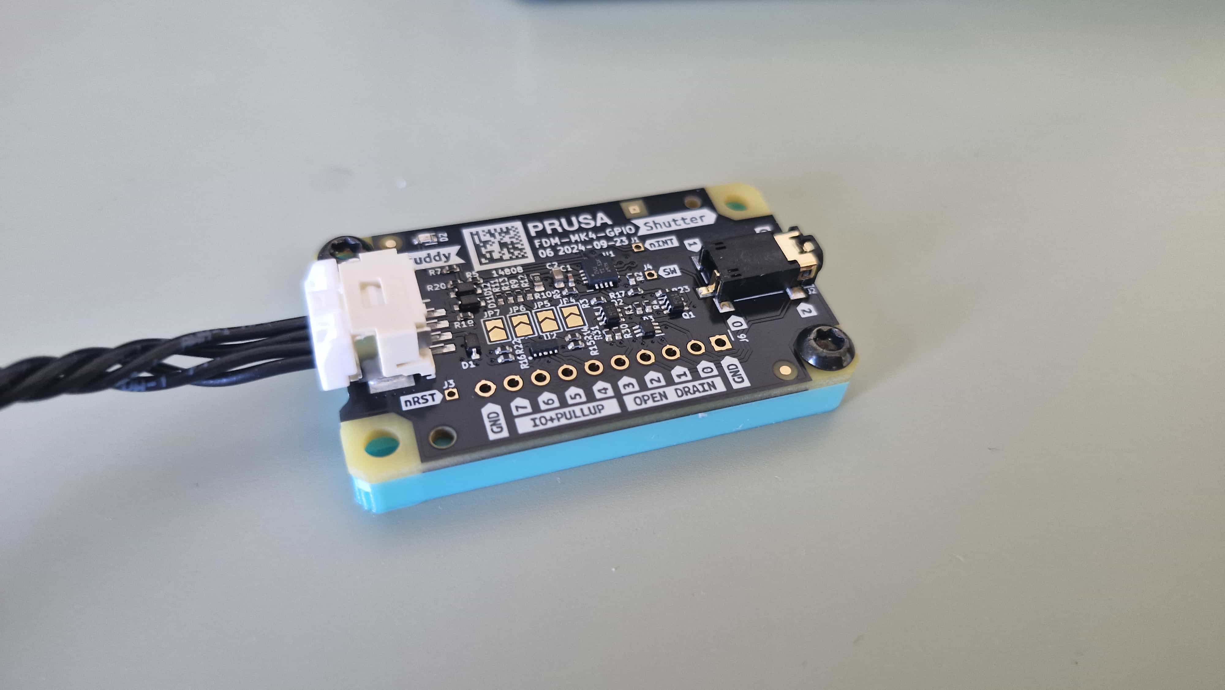
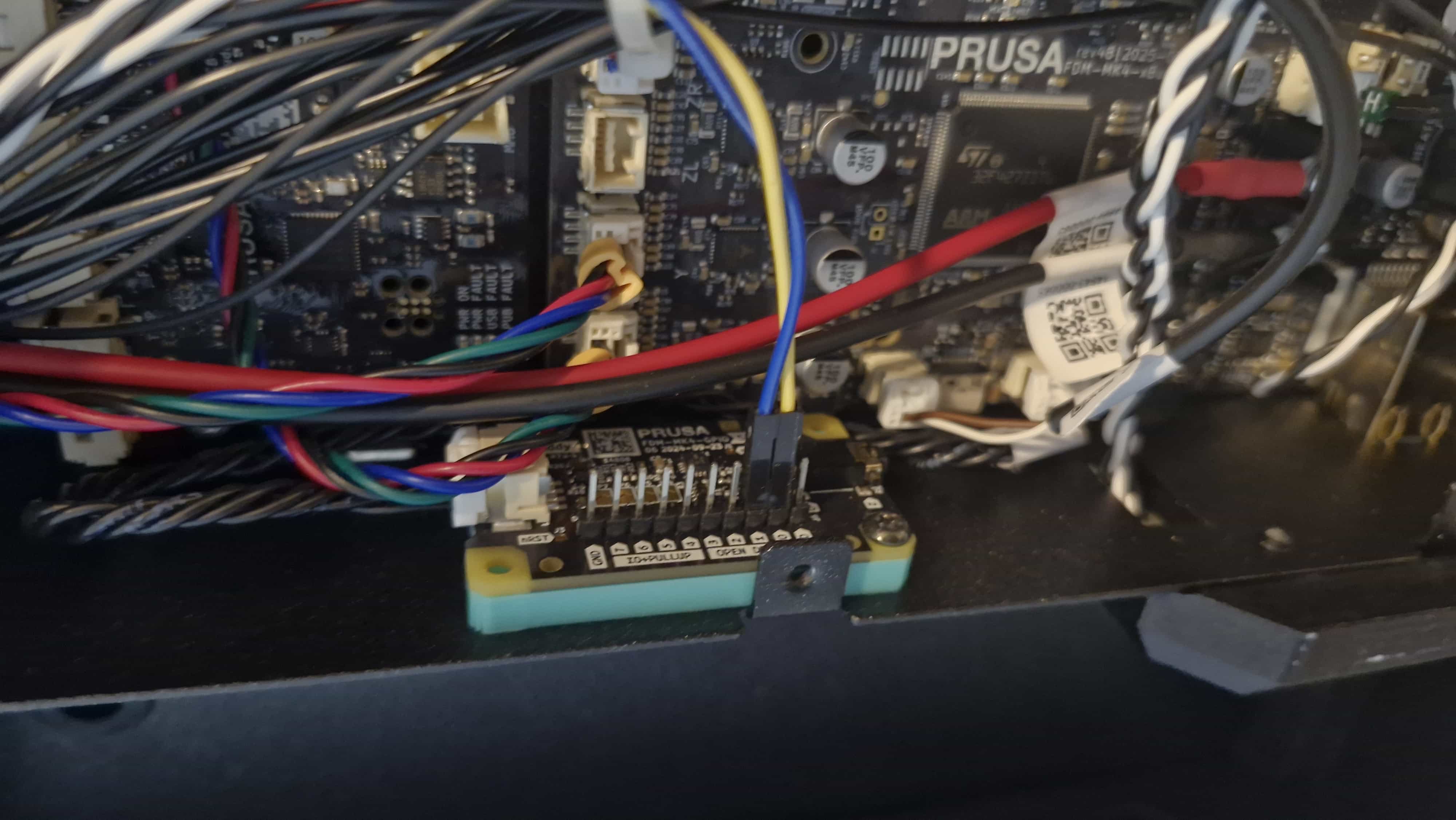
The GPIO Hacker Board is an I2C GPIO expander designed for the Prusa Core One. It allows external hardware to be controlled directly from the printer using G-codes. By embedding specific M-codes into the sliced G-code, the printer can toggle GPIO pins at defined points during a print.
This post documents how I used the GPIO Hacker Board to build a layer-by-layer timelapse system and how I tested and validated the setup efficiently.
How GPIO Control Works on the Core One
When slicing a model, the slicer allows you to insert custom M-codes at predefined stages of the print. These M-codes become part of the final G-code file and are executed by the printer firmware during the print.
Common insertion points include:
- Start of the print
- Before a layer change
- After a layer change
- End of the print
The GPIO Hacker Board listens for these machine codes and updates the state of its GPIO pins accordingly.
GPIO Configuration
Before using the GPIO pins, they must be configured as inputs or outputs. This configuration is typically done in the Start G-code section of the slicer.
For this project:
- All GPIO pins were configured as outputs
- Input functionality was not explored at this stage
Once configured, the pins can be toggled at runtime using M-codes placed at layer changes or other print events.
Timelapse Concept
The goal was to generate a clean layer-by-layer timelapse without relying on printer-mounted cameras or external software.
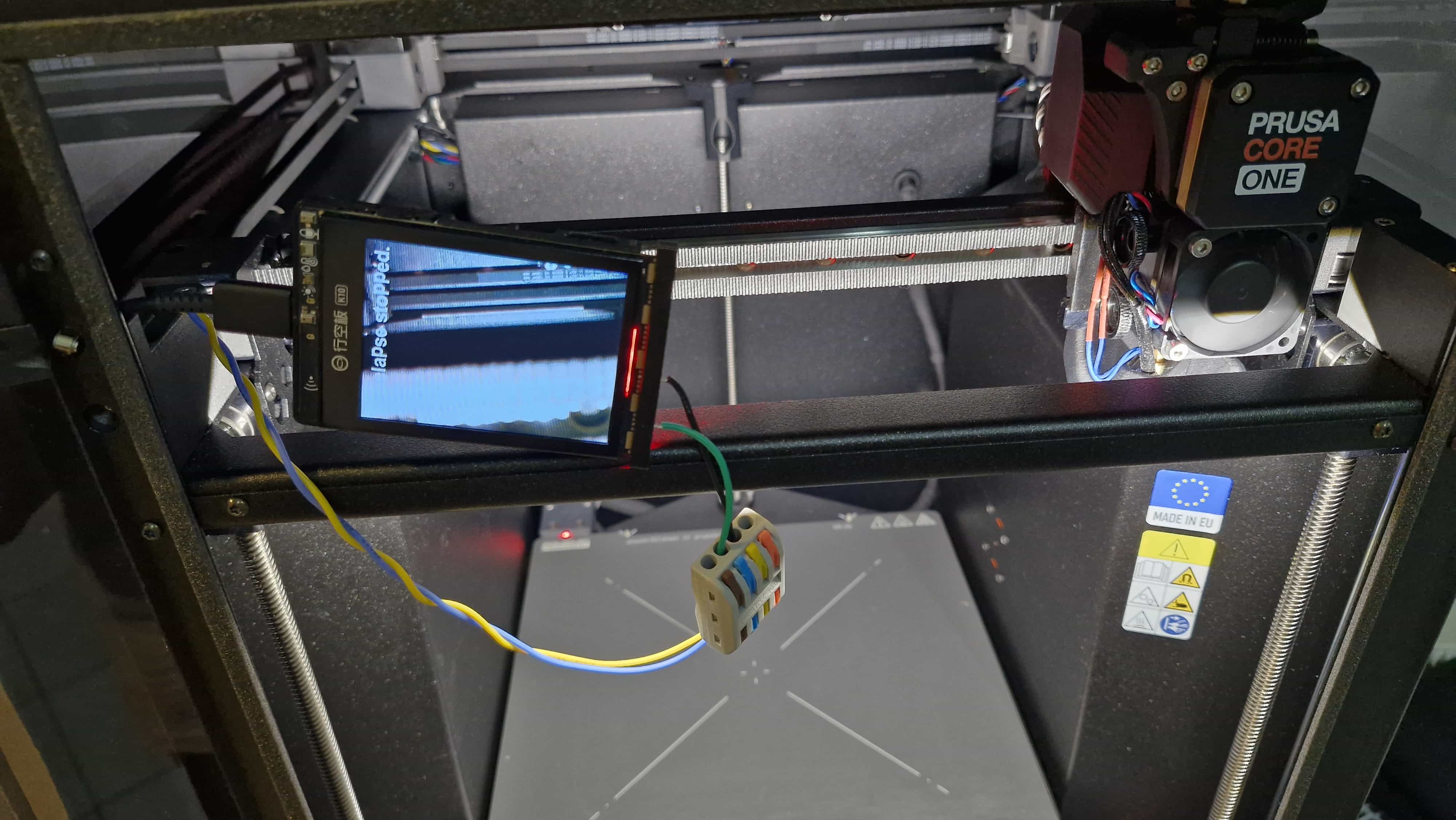
Hardware Used
- UniHiker K10 display module
- Built-in LEDs and two user buttons
- GPIO hacker board
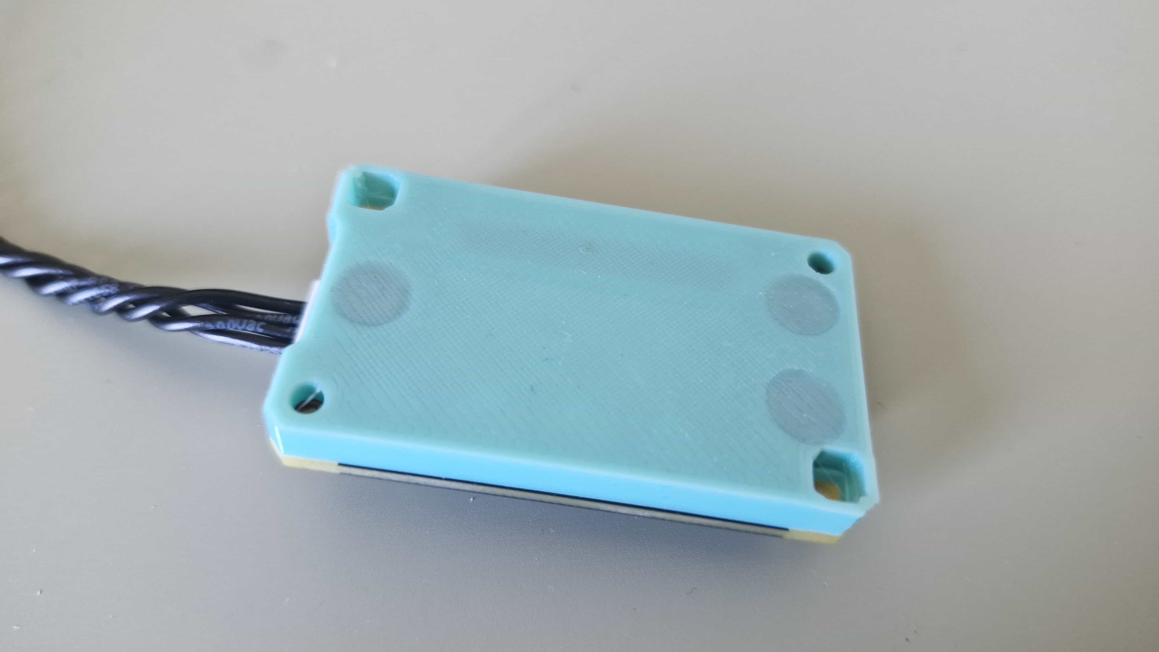
- 3D printed base for hackerboard
Button Mapping Logic
To simplify development and testing, the GPIO outputs from the Core One were mapped to simulate button presses on the UniHiker:
- Button A: Start / stop the timelapse
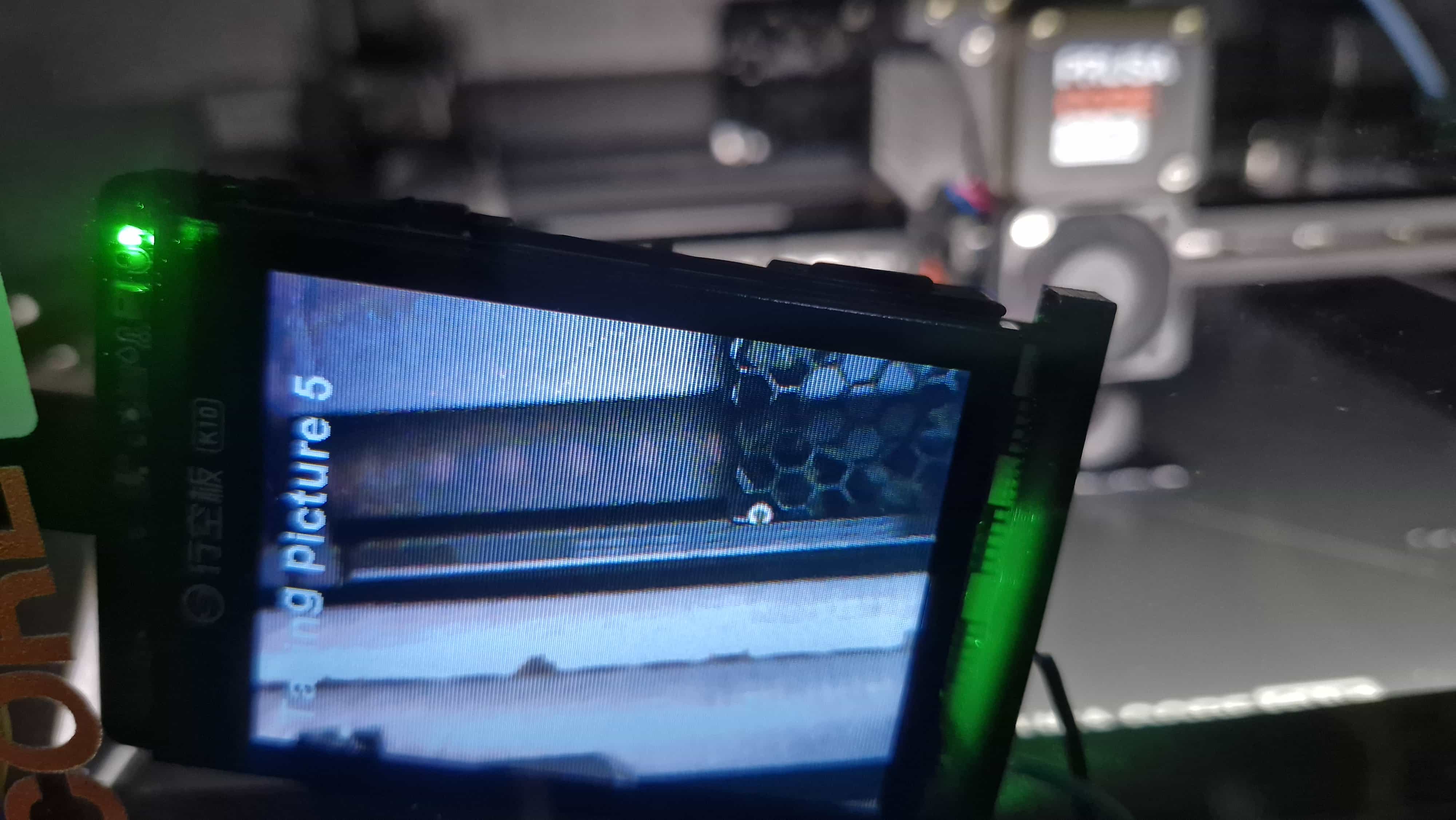
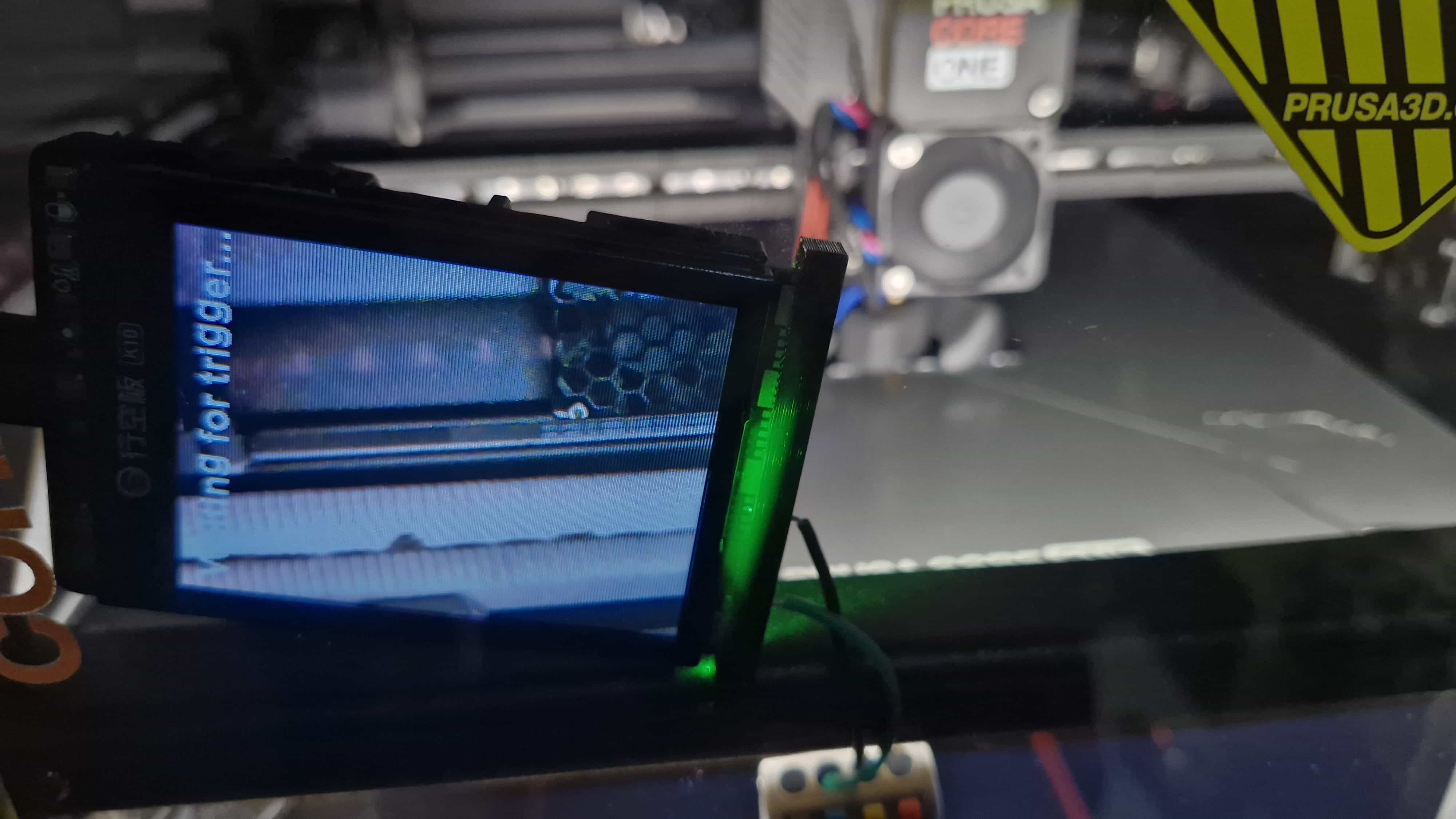
- Button B: Capture an image (triggered at each layer change)
Timelapse Workflow
- Pressing the start button creates a new folder on the SD card
- Each layer-change trigger captures and saves an image into that folder
- LEDs and the display indicate the current system state
- Pressing the start/stop button again ends the timelapse session
This approach allowed the printer to fully control the timelapse process through G-code alone.
Firmware
The UniHiker runs custom Arduino firmware to handle:
- GPIO input detection (simulated button presses)
- Camera triggering
- Folder creation and file management on the SD card
- Status display and LED indicators
Source code link
Testing Strategy
Initial Slicer-Based Testing
The first attempt involved embedding the GPIO M-codes directly into the slicer and running full prints to verify behavior. While functional, this approach resulted in very long feedback cycles.
Alternatives Considered
- OctoPrint terminal testing: Technically viable, but excessive for quick GPIO validation
Final Testing Approach
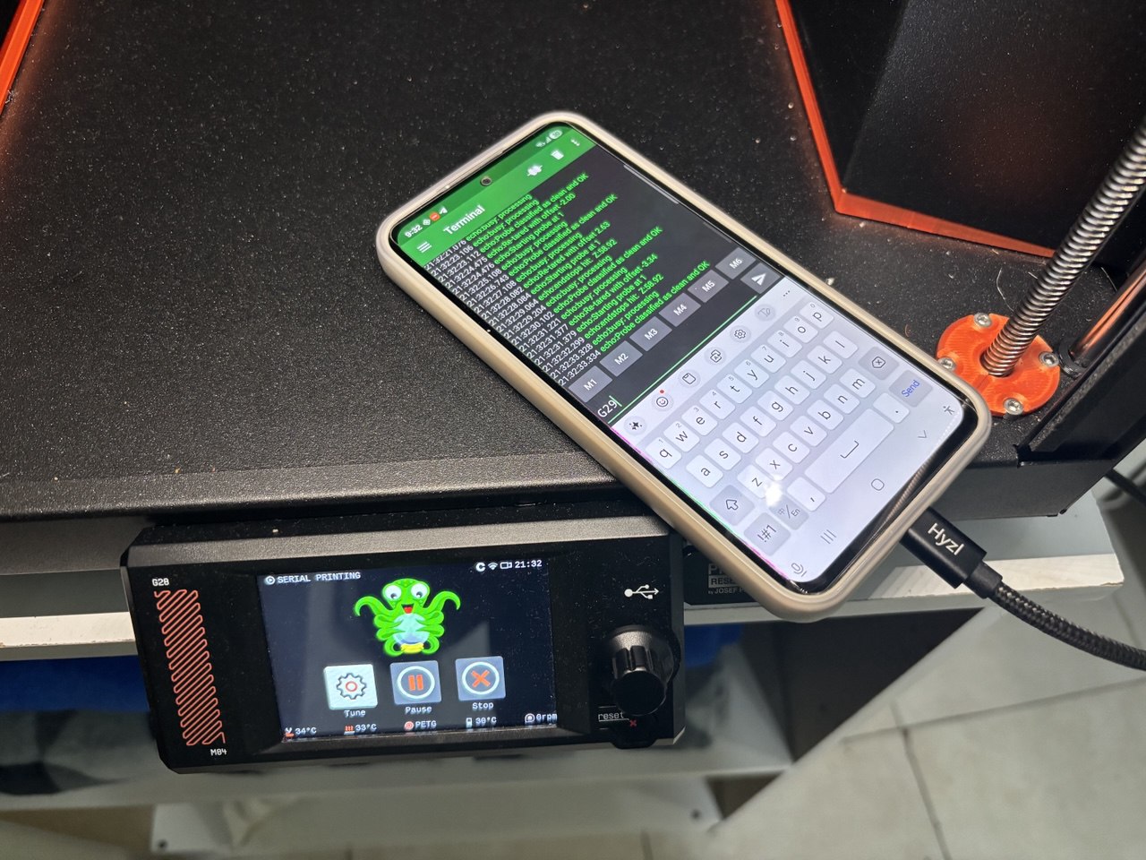
The breakthrough came from realizing that the USB port on the back of the Core One exposes a serial interface.
Steps:
- Connected a smartphone to the printer’s USB port
- Installed a serial terminal application
- Sent G-codes directly to the printer
- Observed GPIO pin state changes in real time
This enabled rapid iteration and immediate validation of GPIO behavior without starting a full print.
Results and Observations
- GPIO triggering via M-codes is reliable and deterministic
- Serial terminal testing dramatically reduces development time
- Simulating button presses is an effective abstraction for external device control
What’s Next
- Explore GPIO input functionality
- Improve camera positioning and enclosure design
- Automate timelapse post-processing

Archives
Tags