Make flowchart with AI prompt tools
As an electronics design engineer, I sometimes need to document my ideas or requirements graphically or create a system architecture. I find this task very time-consuming, even with the drawing tools available that aim to make it as easy as possible.
Here’s an overview of how this can be done:
- Describe the flowchart or architecture: Provide as much detail as possible, using nested bullet points for complex - charts or flows.
- Generate Mermaid code: Ask an AI to generate Mermaid code based on your description.
- Preview the code: Use tools like draw.io or Mermaid Live to paste the code and see a preview.
- Refine the code: If necessary, make adjustments to the code to achieve your desired outcome.
There are some extra steps for draw.io, you’d have to start with a blank chart, then click on the “+” add button > advance > Mermaid
I used the mermaid for quick previews, once its what I want, then I import it in draw.io
Here is an example prompt for making an ESP32 embedded system.
Can you create a Mermaid diagram of an embedded system architecture
with ESP32 as the main controller? Include the following components,
with ESP32 as the central block:

- Programming port using UART0 interface
- 4G module using UART 1 interface
- SD card using SDIO interface
- RS232/RS485 using UART0 (shared with programming port)
- RS232/RS485 2 using UART 2 interface
- IO expander using I2C interface
- RTC using I2C interface
- Battery charger for power management
- 4 digital in with protection
- 2 digital output
- 2 Analog input
- Accelerometer interface
- CAN interface
- Power supply
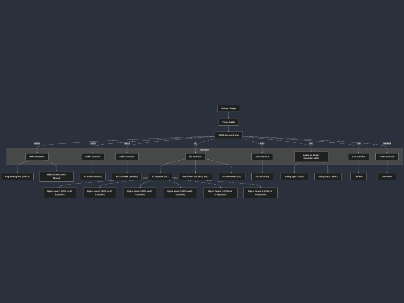
Here is what the final Mermaid output looked like after some refinements.
graph TD
    %% Central Controller
    ESP32["ESP32 Microcontroller"]

    %% Interfaces
    subgraph Interfaces
        direction TB
        UART0["UART0 Interface"]
        UART1["UART1 Interface"]
        UART2["UART2 Interface"]
        I2C["I2C Interface"]
        SDIO["SDIO Interface"]
        ADC["Analog-to-Digital Converter (ADC)"]
        CAN["CAN Interface"]
        OneWire["1-Wire Interface"]
    end

    %% Components
    ProgPort["Programming Port (UART0)"]
    G4Module["4G Module (UART1)"]
    SDCard["SD Card (SDIO)"]
    RS232_RS485_1["RS232/RS485 (UART0 Shared)"]
    RS232_RS485_2["RS232/RS485 2 (UART2)"]
    IOExpander["IO Expander (I2C)"]
    RTC["Real-Time Clock (RTC) (I2C)"]
    BatteryCharger["Battery Charger"]
    DigitalIn1["Digital Input 1 (GPIO via IO Expander)"]
    DigitalIn2["Digital Input 2 (GPIO via IO Expander)"]
    DigitalIn3["Digital Input 3 (GPIO via IO Expander)"]
    DigitalIn4["Digital Input 4 (GPIO via IO Expander)"]
    DigitalOut1["Digital Output 1 (GPIO via IO Expander)"]
    DigitalOut2["Digital Output 2 (GPIO via IO Expander)"]
    AnalogIn1["Analog Input 1 (ADC)"]
    AnalogIn2["Analog Input 2 (ADC)"]
    Accelerometer["Accelerometer (I2C)"]
    CANPort["CAN Port"]
    OneWirePort["1-Wire Port"]
    PowerSupply["Power Supply"]

    %% Connections to ESP32
    ESP32 -->|UART0| UART0
    ESP32 -->|UART1| UART1
    ESP32 -->|UART2| UART2
    ESP32 -->|I2C| I2C
    ESP32 -->|SDIO| SDIO
    ESP32 -->|ADC| ADC
    ESP32 -->|CAN| CAN
    ESP32 -->|OneWire| OneWire

    %% Interface Connections
    UART0 --> ProgPort
    UART0 --> RS232_RS485_1
    UART1 --> G4Module
    UART2 --> RS232_RS485_2
    I2C --> IOExpander
    I2C --> RTC
    I2C --> Accelerometer
    SDIO --> SDCard
    BatteryCharger --> PowerSupply
    IOExpander --> DigitalIn1
    IOExpander --> DigitalIn2
    IOExpander --> DigitalIn3
    IOExpander --> DigitalIn4
    IOExpander --> DigitalOut1
    IOExpander --> DigitalOut2
    ADC --> AnalogIn1
    ADC --> AnalogIn2
    CAN --> CANPort
    OneWire --> OneWirePort
    PowerSupply --> ESP32
And here is the generated flowchart
Once the code is previewed, you can always ask for refinments such as moving certain block around or nesting some block under others etc.
This has save me a ton of time. Hope this helps you too.
Archives
Tags