Powering the System
Guide to power supply design.
Power supply is one of the most critical components in any product, If the power supply is not reliable, the whole product becomes unreliable regardless of how well the rest of the system is designed, all that effort goes to waste. If the power supply design is not proper, you’d have boot loops, and sometimes even bricked devices. Understanding power supply design is essential for anyone building embedded systems
Ideal power supply
Let’s start by looking at how an idea power supply looks like
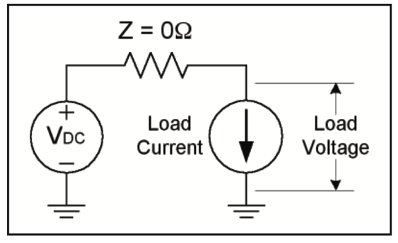 The ideal power supply supplies the rated DC voltage at all frequencies. Almost all of electronics is digital, and the digital electronics are made of CMOS, these consume power in discreet manner. We see the current consumption is not stable, we see spikes, we see spikes even more so in wireless devices, that consume more than average current during data transmission. But in real life the input impedance is not zero and it changes with frequency.
System Requirements
Next, step in our design is creating a power budget. This entails making a spreadsheet and listing down all the components that consume power. The major components are
- Main processor
- Peripherals
- NVME, Wi-Fi, SATA HDD, USB hub, USB-C, Sensors
Power Budget
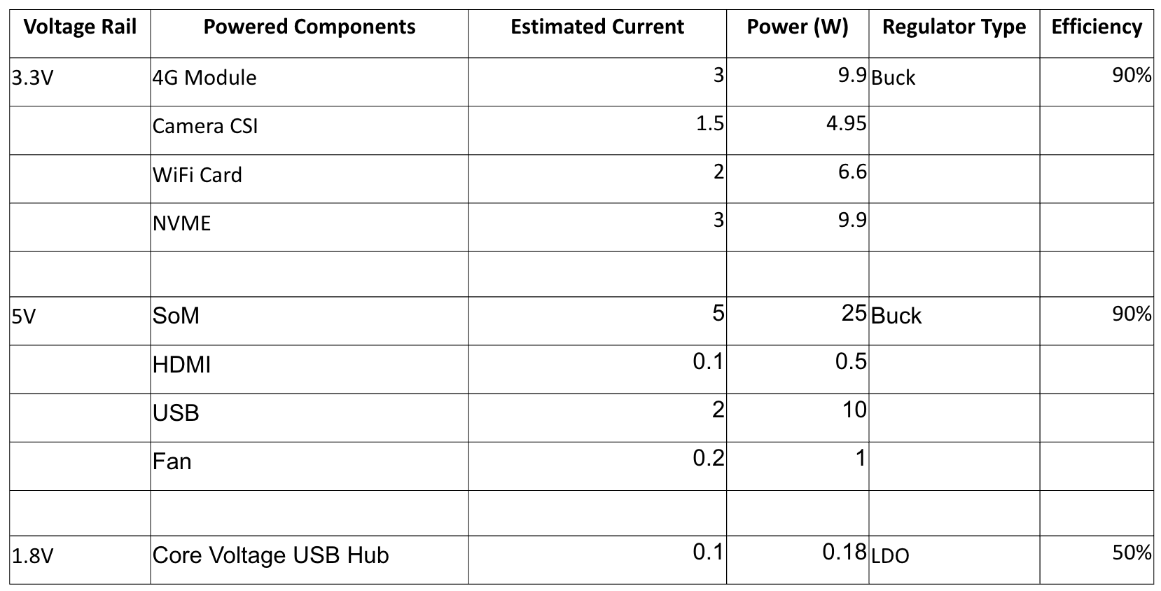
We find for each component the rated voltage, its tolerance and average and peak current consumption. Then we can get the average and peak power needed for each rail. We usually find the voltage and current parameters in the data-sheet. Next, we check if there are any power sequencing requirements and also list it out and use a micro-controller to control the enable lines signals.
Architecture
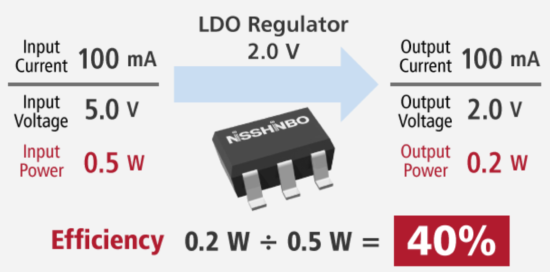
After this we create the architecture. We go a little deeper in the power supply design. Here we fix what kind of regulators we will use for getting each voltage rail. We also find the efficiency of each method and list it out in the power budget and add details about the type of regulator we are using and its efficiencies. We compensate for the current requirements.
We find what is the total power loss in the system. The power loss helps us identify if we well need a heat sink and roughly how big. Sizing the thermals is a separate exercise.
Power tree
Creating a power tree also helps in visualizing how to voltage rails are derived.
+12V
└──Buck── +5V Input
├── Display Backlight (direct)
├── USB Device (direct)
├── Fan (via MOSFET switch)
├──→ LDO → 3.3V → I2C Sensors, RTC
│                         └──→ LDO → 1.8V Optional Sensor
└── VBAT (isolated coin cell to RTC)
Power Inputs
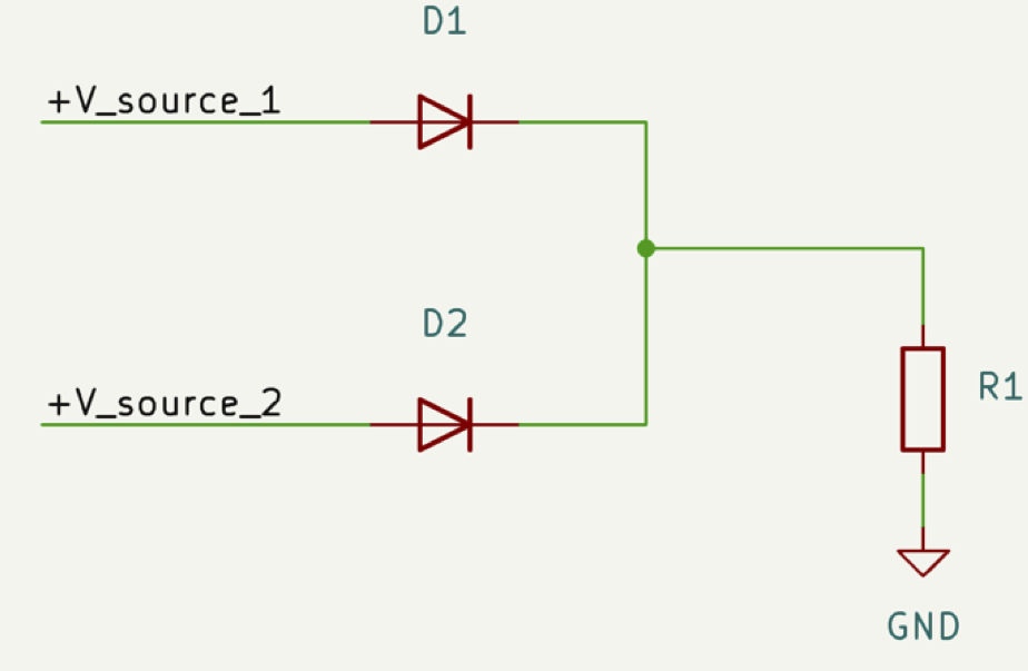
We need to know what our power inputs are going to be. What sort of noise we can expect. Usually if the device is low power, it can be powered by USB and or battery. If high power is needed it can use industrial voltages lik+12V or 24V or even +48V. Some devices are also powered by PoE. In some cases, they could be powered by solar power too. When two or more power options are present, you need to use power OR-ing in order to select one power supply option. There are many ways to do this.
When inputs are selected, you need to also add some protections in order to protect your device, in case if power supply supplies more voltage than needed, reverse polarity protection. Also, you need to protect the power supply if the device malfunction and causes short circuit, in this case using fuses is a must.
Decoupling caps
When using any power topology, usually there is an input filtering capacitor and also an output capacitor to filter the noise from the switching regulators. And also, to keep up with the load as sometimes the load can demand current faster than the power supply is capable of.
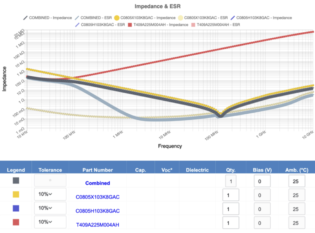
Below is a graph of the impedance profile when multiple caps are used in the system.
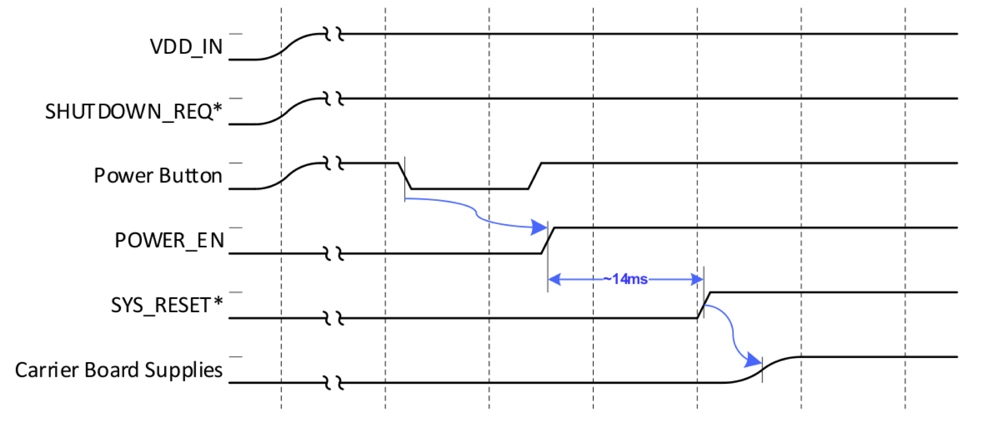
Power sequencing
Next, with our power supply present, you need to make sure the voltages are enabled in the proper manner as needed by the SoM, this is not needed by micro-controller designs.
Below is a power up sequence of Jetson nano SoM
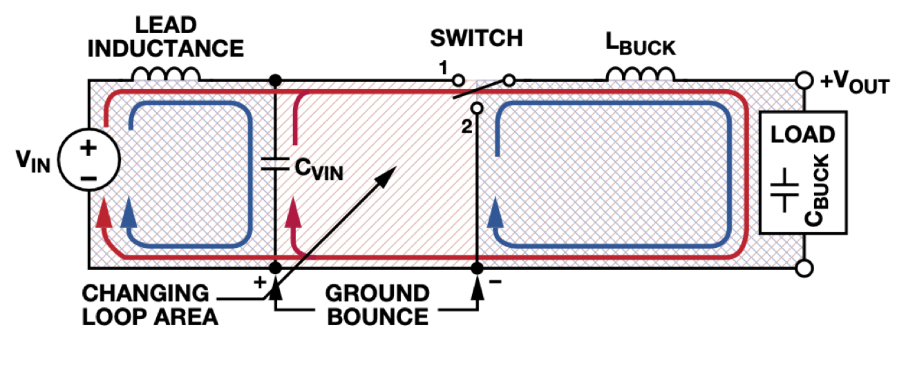
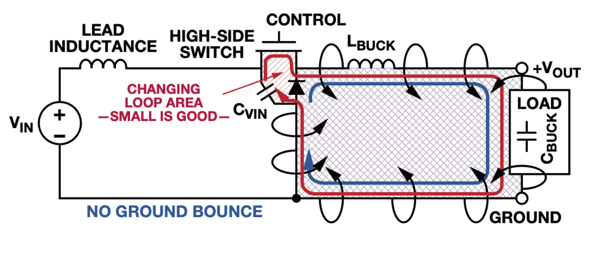
Layout tips
Need to make sure the power traces are wide enough not only for peak load currents by also for the inrush current. Also, you need to make sure the caps and inductors make smaller loops in both on and off condition of the switcher. This helps with reducing the ground bounce. It’s better to have the switching section in one part of the PCB, this helps in isolate the noise.
You need to make sure to use a proper layer stack to distribute the power across the board, and make sure they are coupled with ground, as having a capacitor in the PCB helps with noise issues. Make sure you don’t route between gnd and V layers. The copper plane also works as heat sinks, but you need to make sure the PCB not over heat as that will cause other host of issues. Add test points for all the rails so that you can monitor them. This will help in trouble shooting.
Test and measurement
This is a topic on its own, but we will list all the important things we need to measure.
- ripple voltage
- real efficiency of the converter
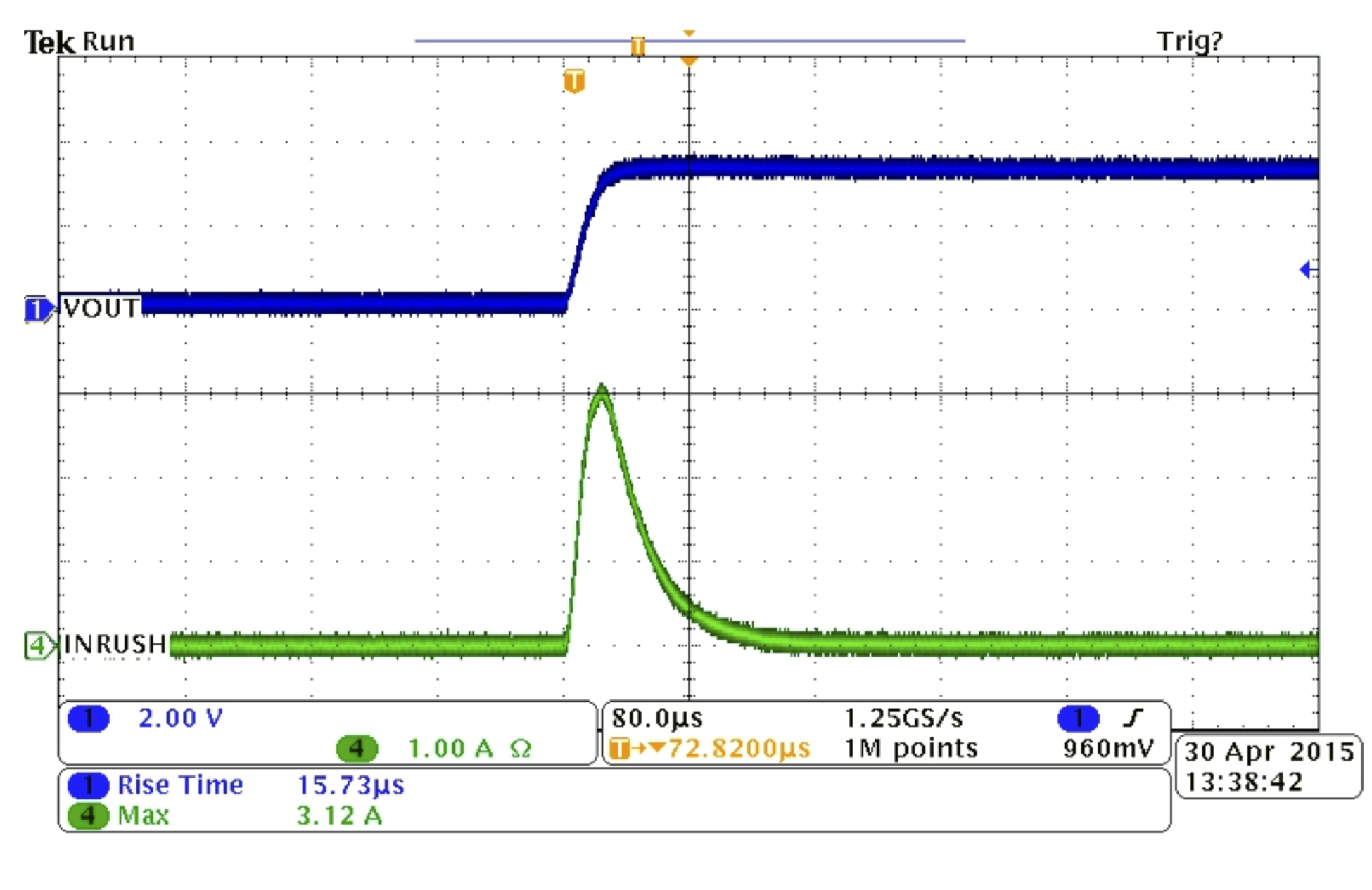
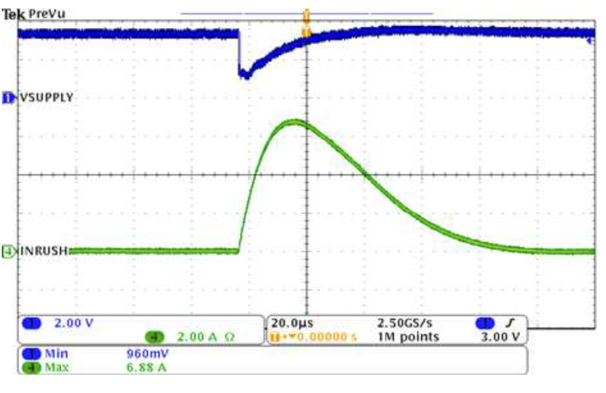
- inrush current
- reverse polarity
- over voltage
- short circuit
- functional test
In order for performing these tests, its important to have the provisions on the PCB. Things like test points for voltage measurement, solder bridges for current measurement.
Trouble shooting
Ground bounce causes EMI issues and the signals can get affected. Also measure the inrush current. If it’s too high, it’s better to reduce the capacitance of the system, so during turn on there are less caps to charge. Also size the trace to accommodate the inrush current.
Resources
Below are the resources I use while designing the power supply system. TI webench Analog Power tools KSIM App notes from manufacturers.
Archives
Tags